Multiple transmitter and receiver well logging device with error calibration system including calibration injection system

a multi-signal and receiver technology, applied in the field of well logging, can solve the problems of long well tools that not only require additional materials and cost more to manufacture, but are more likely to bind or stick, and achieve the effect of simple calibration methods and less complex

Inactive Publication Date: 2007-02-27
ULTIMA LABS
View PDF15 Cites 9 Cited by
  • Summary
  • Abstract
  • Description
  • Claims
  • Application Information

AI Technical Summary

Benefits of technology

[0045]An advantage of the present invention includes that the device and method provides a means to correct, in real time, data acquisition errors of propagation wave devices that use multiple receivers to measure propagation parameters such as attenuation and phase difference.
[0046]Another advantage of the present invention is that the disclosed calibration method is less complex as compared to other methods that use depth alignment of similar propagation measurements to determine errors introduced by the receiver data acquisition electronics.
[0047]Yet another advantage is a simpler calibration method that requires no borehole depth information. Another advantage is the elimination of errors related to the time drift of electronic parameters. Still yet, another advantage is the downhole computation in real time of calibrated dual-receiver propagation measurements.

Problems solved by technology

Long well tools not only require additional material and cost more to manufacture but they are more likely to bind or stick in narrow or deviated boreholes.
This problem is particularly acute in multilateral wellbores having a reduced entry radius and in highly deviated wellbores.

Method used


Image

  • Multiple transmitter and receiver well logging device with error calibration system including calibration injection system
  • Multiple transmitter and receiver well logging device with error calibration system including calibration injection system
  • Multiple transmitter and receiver well logging device with error calibration system including calibration injection system

Examples


Embodiment Construction

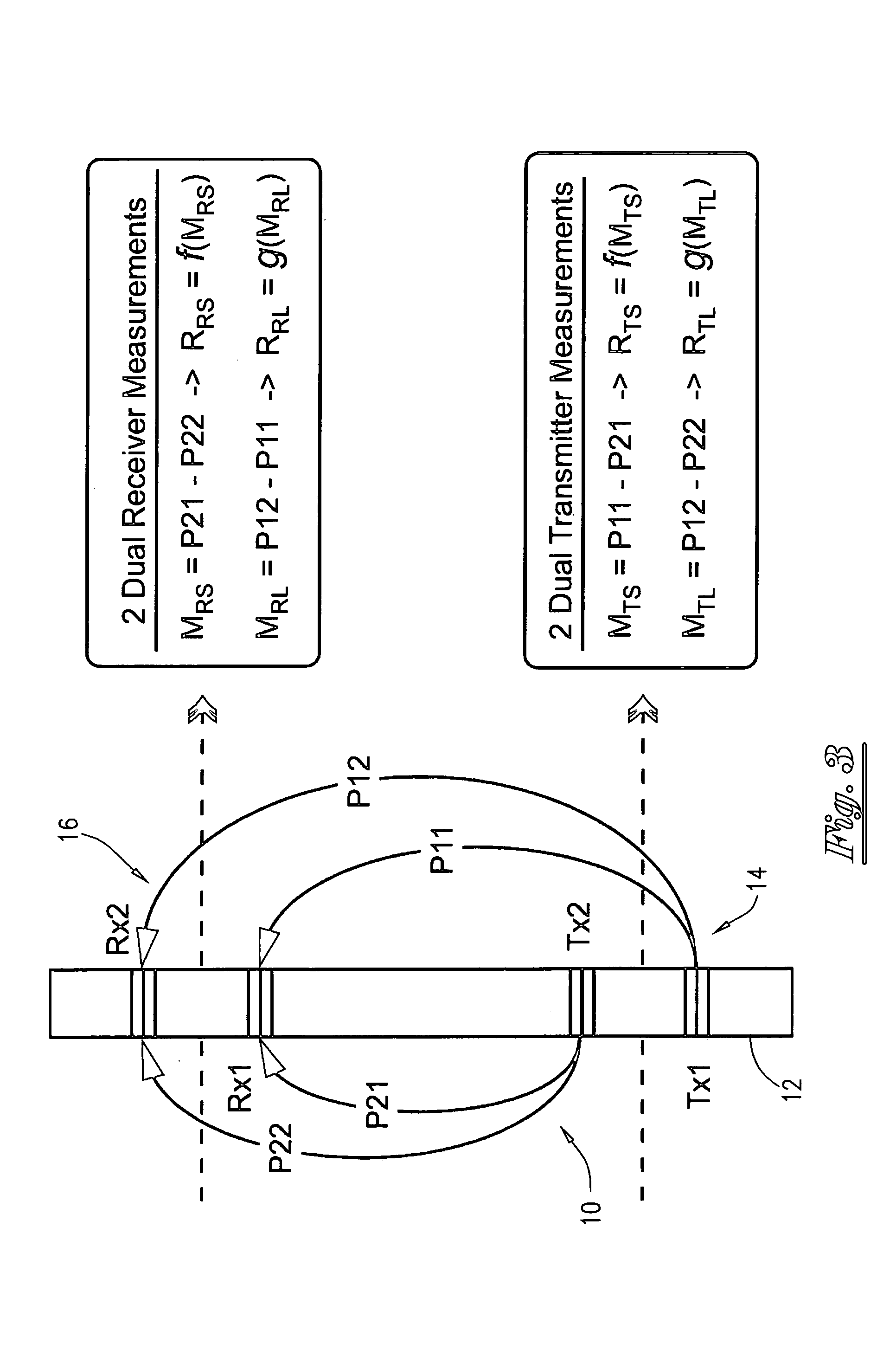
[0061]The invention provides a unique propagation wave resistivity system. The system is capable of providing two depths of investigation as shown in FIG. 3. Tool 10 comprises tool body 12 carrying two transmitters identified as transmitter pair 14 and two receivers identified as receiver pair 16. First transmitter Tx1 is located proximate to second transmitter Tx2. Located at a selected distance from transmitter pair 14 are first receiver Rx1 and second receiver Rx2.

[0062]Property P11 illustrates the electromagnetic property of the propagation path from first transmitter Tx1 to first receiver Rx1. Property P12 illustrates the electromagnetic property of the propagation path from first transmitter Tx1 to second receiver Rx2. Similar properties are illustrated for second transmitter Tx2, wherein property P21 illustrates the propagation path from second transmitter Tx2 to first receiver Rx1, and P22 illustrates the propagation path from second transmitter Tx2 to second receiver Rx2.

[0...


PUM


Abstract

A device and method for obtaining an electromagnetic propagation measurement of a subterranean geologic formation, with the formation being intersected by a borehole. The device comprises a transmitter for transmitting an electromagnetic signal, and a first and second receiver for receiving the transmitted signal. The device further comprises a circuit for injecting a calibration signal into the first receiver and the second receiver, and a processor for processing the uncalibrated receiver signal and the calibration signal to obtain electromagnetic propagation measurement that is free from errors introduced by the receiving elements of the system. The processor may include a receiver data acquisition circuit for correcting data acquisition errors related to the first receiver and the second receiver.

Description

[0001]This application is a continuation-in-part application of my presently application Ser. No. 10 / 237,439, filed on 9 Sep. 2002 now U.S. Pat. No. 6,822,455.BACKGROUND OF THE INVENTION[0002]This invention relates to the field of well logging. More specifically, the invention relates to a novel apparatus and techniques for eliminating data acquisition errors inherent in electromagnetic propagation wave devices. The invention also relates to an apparatus and method for measuring the resistivity of geologic formations surrounding a borehole during well logging and logging while drilling operations.[0003]Formation resistivity is commonly used to evaluate geologic formations surrounding a borehole. Formation resistivity indicates the presence of hydrocarbons in the geologic formations. Porous formations having high resistivity generally indicate that they are predominantly saturated with hydrocarbons, while porous formations with low resistivity indicate that such formations are predom...

Claims


Application Information

Patent Timeline
Patent Type & Authority Patents(United States)
IPC IPC(8): G01V3/12G01V1/44
CPCG01V1/44G01V13/00G01V3/30
Inventor FLANAGAN, WILLIAM D.
Owner ULTIMA LABS
Why Eureka
Try Eureka