Circuits and methods for detecting phase lock

a phase lock and circuit technology, applied in the direction of oscillator tubes, pulse automatic control, electrical equipment, etc., can solve the problems of incorrect generation of lock detection signals and inability to accurately perform lock detection

Active Publication Date: 2007-02-27
SAMSUNG ELECTRONICS CO LTD
View PDF18 Cites 13 Cited by
  • Summary
  • Abstract
  • Description
  • Claims
  • Application Information

AI Technical Summary

Benefits of technology

[0039]According to the present invention, the phase-locked loop circuit and method are capable of outputting the lock detection signal when the locking of phase is completed using the characteristics of respective operating regions of the phase-locked loop circuit.

Problems solved by technology

However, according to Japanese Patent Application Laid-Open Publication No. 2002-344312, in some situations, lock detection cannot be accurately performed due to noise, and, in those cases, a lock detection signal can be incorrectly generated when the PLL circuit is not in an entirely locked state.

Method used


Image

  • Circuits and methods for detecting phase lock
  • Circuits and methods for detecting phase lock
  • Circuits and methods for detecting phase lock

Examples


Embodiment Construction

[0056]The present invention will now be described more fully hereinafter with reference to the accompanying drawings, in which preferred embodiments of the invention are shown. This invention may, however, be embodied in different forms and should not be construed as limited to the embodiments set forth herein. Like numbers refer to like elements throughout the specification.

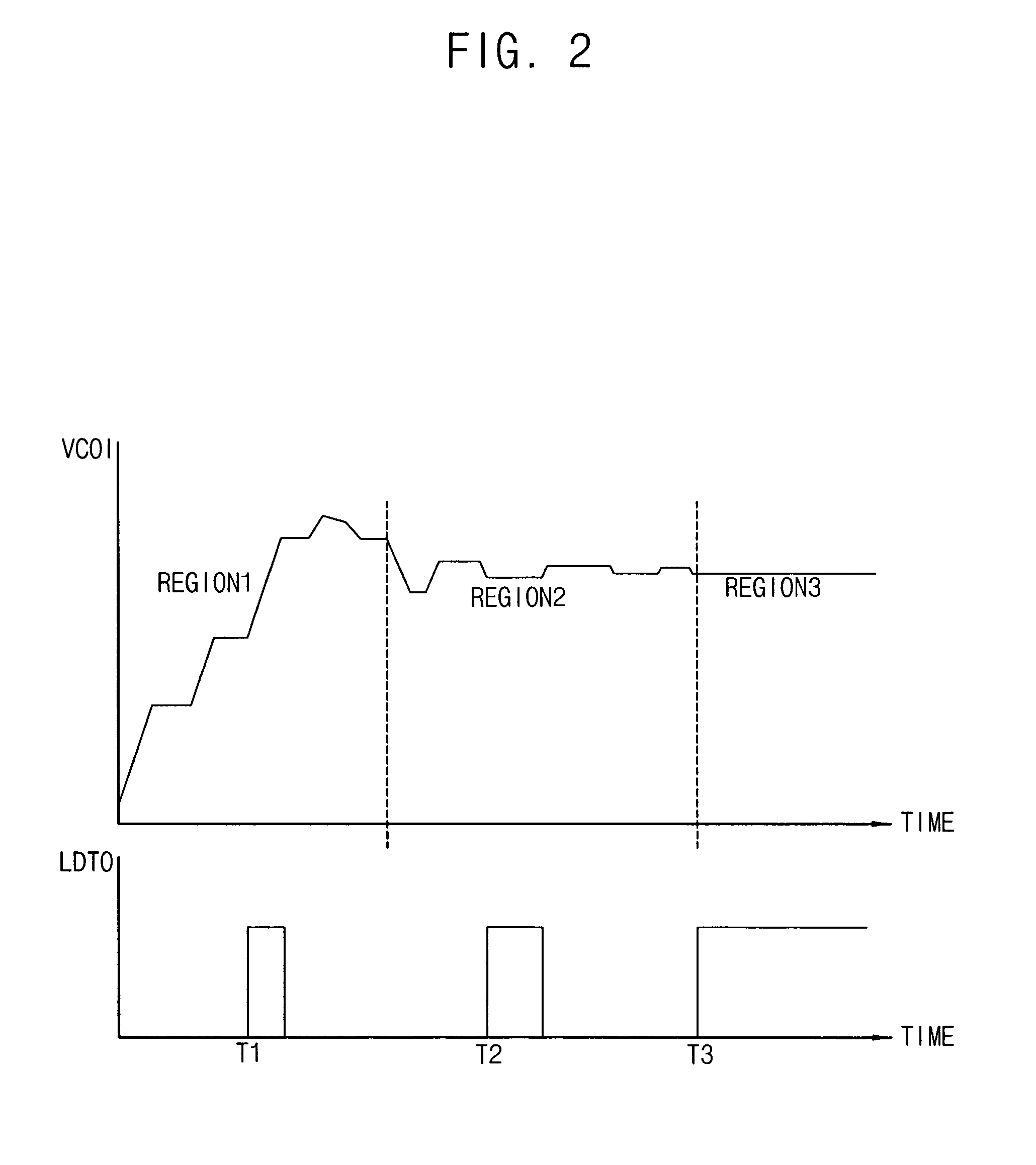
[0057]FIG. 2 is a diagram showing the operation of a PLL circuit and generation of a lock detection signal according to an example embodiment of the present invention.

[0058]As shown in FIG. 2, the PLL circuit can have three operating regions, first, second and third operating regions REGION1, REGION2 and REGION3, in accordance with the lapse of time occurring from power-on of a voltage-controlled oscillator (VCO) to the locking of the PLL circuit. In the first operating region REGION1, an input signal VCOI of the VCO, which is a component circuit block of the PLL circuit, has a level that increases continuously....


PUM


Abstract

In a phase-locked loop circuit including a lock detection function, the phase-locked loop circuit includes a lock detection circuit. The lock detection circuit includes a lock-window-entry detection circuit and a lock-detection-signal generation circuit. The lock-window-entry detection circuit detects a front edge of an up signal or a down signal generated by a phase frequency detector at a front edge of a delayed up signal or a delayed down signal to generate a lock-window-entry detection signal, wherein the delayed up signal or the delayed down signal is delayed substantially by as much as a lock window. The lock-detection-signal generation circuit counts an input signal of a phase-locked loop circuit to generate a lock detection signal when the lock-window-entry detection signal is continuously enabled for a predetermined time period. In this manner, a lock detection signal is output only when the phase locking operation has been completed.

Description

CROSS-REFERENCE TO RELATED APPLICATIONS[0001]This application relies for priority upon Korean Patent Application No. 2004-58592 filed on Jul. 27, 2004, the contents of which are herein incorporated by reference in their entirety.BACKGROUND OF THE INVENTION[0002]1. Field of the Invention[0003]The present invention relates to a phase-locked loop circuit, and particularly to a phase-locked loop circuit capable of providing a lock detection signal after achieving a phase lock state.[0004]2. Description of the Related Art[0005]Phase-locked loop (PLL) circuits are one of the basic building blocks in modern electronic systems. They have enjoyed widespread use in communications, multimedia, and other applications. Frequency synthesizers, FM demodulators, clock recovery circuits, modems, and tone decoders are examples of applications that employ PLL circuits.[0006]The PLL circuit is a negative feedback control system. As shown in FIG. 1, the PLL circuit generally includes a phase-frequency d...

Claims


Application Information

Patent Timeline
Patent Type & Authority Patents(United States)
IPC IPC(8): H03L7/095
CPCH03L7/0891H03L7/095Y10S331/02H03L7/087
Inventor JUNG, WOO-YOUNG
Owner SAMSUNG ELECTRONICS CO LTD
Why Eureka
Try Eureka