

Camera having flexible display
a technology of flexible display and camera, which is applied in the field of flexible display of cameras, can solve the problems of reducing the size of the camera, occupying a space,
- Summary
- Abstract
- Description
- Claims
- Application Information
AI Technical Summary
Benefits of technology
Problems solved by technology
Method used
Image

Examples
embodiment 1
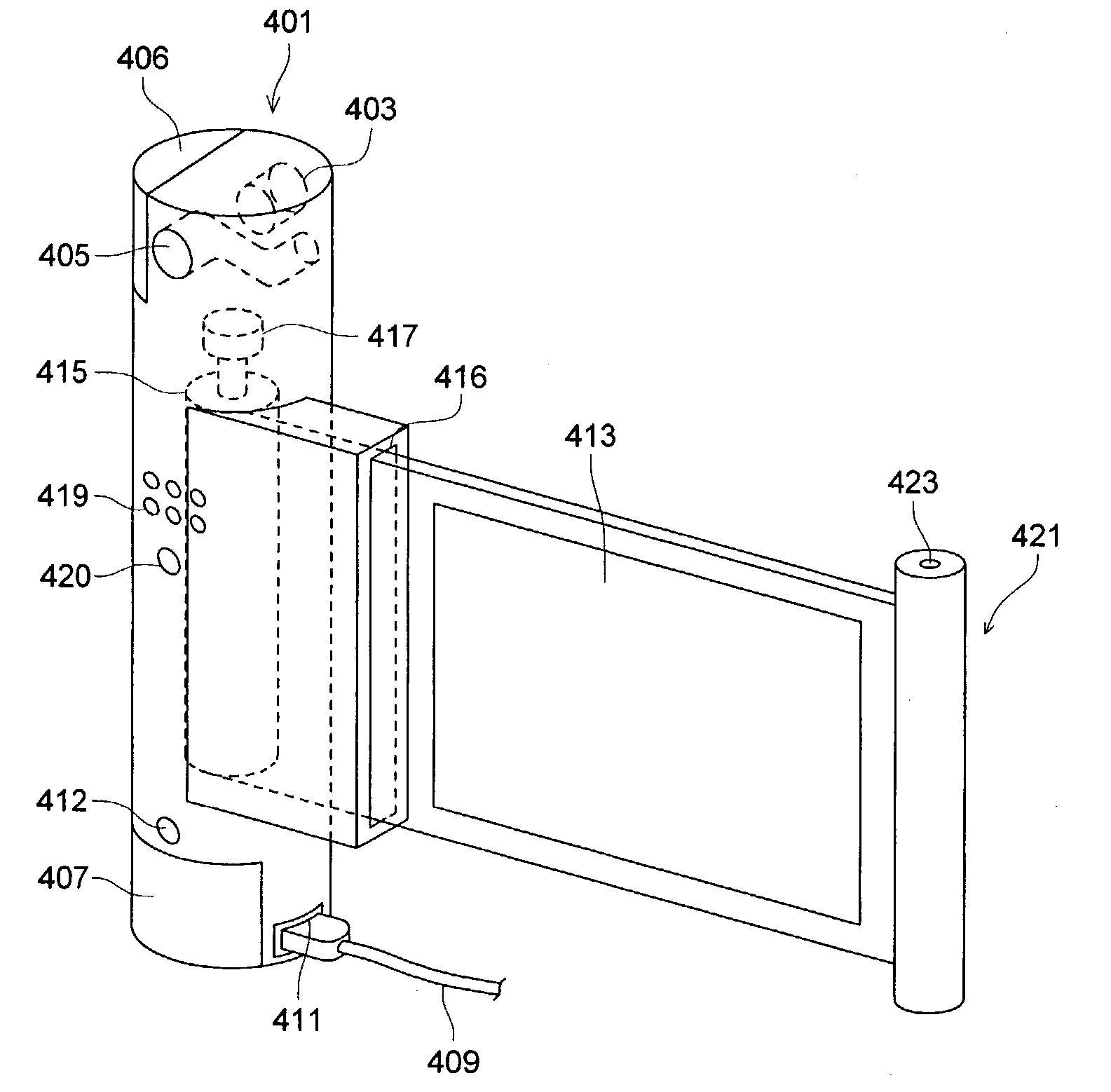
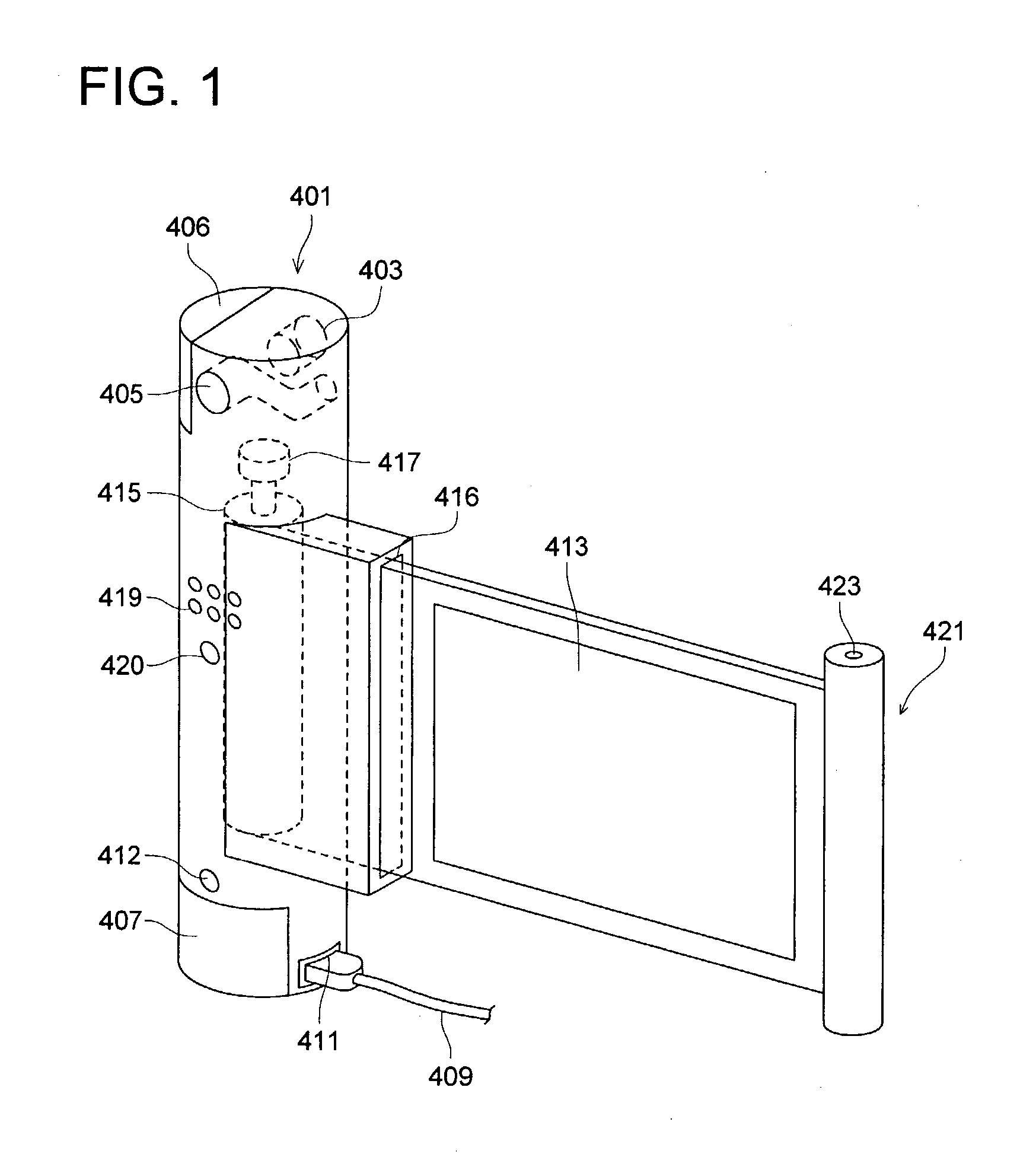
[0110]Initially, referring to FIG. 1, the appearance shape of a camera of Embodiment 1 will be described. In the view, on the upper portion of a columnar camera main body portion 401, a photographing lens 403 and an optical viewfinder 405 are provided. Hereupon, in the optical viewfinder of the present embodiment, a viewfinder light shielding means (not shown) for shielding the light in the optical path of the optical viewfinder is provided. Hereupon, in the present embodiment, the viewfinder light shielding means is structured such that it shields the light in the optical path of the optical viewfinder. However, even when it is structured such that the light is shielded at either portion of an objective portion or an ocular portion of the optical view finder, it may be allowable.
[0111]Further, there is provided on the upper portion of the camera main body 401, a memory card cover 406 for putting-in and putting-out of the memory card in which the photographed image is recorded. Ther...
embodiment 2
[0155]Referring to FIGS. 3(a) and 4(b) showing Embodiment 2, the explain will be made. Hereupon, FIG. 3(a) is a perspective view viewing the camera from the photographer side, and FIG. 3(b) is a view viewing the camera from the object side.
[0156]The photographing lens 3 is provided on the camera main body portion 1. Further, one end portion side of the flexible display 7 is attached to the camera main body portion 1, and it can be taken-up in the camera main body portion 1. In the view, the flexible display 7 can be take-up inside the camera main body portion 1 through a slit 9 of the camera main body portion 1.
[0157]On one hand surface (the surface of the photographer side) of the display 7, the display portion 11 on which the image is displayed is formed, and on the other hand surface (the object side), the flexible solar battery 13 is provided.
[0158]According to the above-described structure, because the display 7 has the flexibility, and can be taken-up in the camera main body 1...
embodiment 3
[0162]Referring to FIG. 4 showing Embodiment 3, the explain will be made. On the camera main body portion 21, the photographing lens 23 is provided.
[0163]Further, one end portion side of the flexible display 27 is attached to the camera main body portion 21, and it can be taken-up in the camera main body portion 21. In the view, the flexible display 27 can be taken-up inside camera main body portion 21 through a slit 29 of the camera main body portion 21.
[0164]On one hand surface (the surface of the photographer side) of the display 27, the display portion 31 on which the image is displayed, and the flexible solar battery 33 is provided.
[0165]According to the above-described structure, because the display 27 has the flexibility, and can be taken-up in the camera main body 21, the camera becomes compact, and is handy to carry.
[0166]Further, when the solar battery 33 is provided on the same surface as the surface (display surface) on which the display section 31 of the display 27 is p...
PUM
 Abstract
Description
Claims
Application Information