
Modular RF terminal having integrated bus structure

a module and bus technology, applied in the direction of electrical apparatus casings/cabinets/drawers, electrical apparatus connection connections, casings/cabinets/drawers details, etc., can solve the problem of reducing the throughput supported by the bus with respect to individual signals, the amount of space required, and the inability to realize the miniaturization of rf and transceiver components and packaging

Active Publication Date: 2007-02-27
HARRIS CORP
View PDF17 Cites 52 Cited by
  • Summary
  • Abstract
  • Description
  • Claims
  • Application Information

AI Technical Summary

Problems solved by technology

However, miniaturization of RF and transceiver components and packaging cannot be realized without overcoming a number of technical obstacles.
One particularly difficult problem that arises with attempts to minimize transceiver size is how to reduce the amount of space required for wiring and signal conductors that convey signals to various analog and digital processing circuitry within the transceiver.
However, every digital bus has a maximum speed of operation, and time sharing among multiple signals effectively reduces the throughput supported by the bus with respect to individual signals.
Thus, signal bus requirements can become a major impediment to reducing the size of electronic devices that digitally process RF signals.
In a practical context, the problem of digital bussing becomes unmanageable when attempting to develop a reduced-size RF transceiver capable of supporting a phased-array antenna, since each antenna element transmits and receives separate RF signals, each of which involves processing of multi-bit digital samples.
More generally, given the variety of sensing, communication and navigation capabilities required throughout a complex, multifunctional system, such as that contemplated by the ESE mission, there are considerable risks associated with development time, development, equipment and operational costs, and system reliability.

Method used


Image

  • Modular RF terminal having integrated bus structure
  • Modular RF terminal having integrated bus structure
  • Modular RF terminal having integrated bus structure

Examples


Embodiment Construction

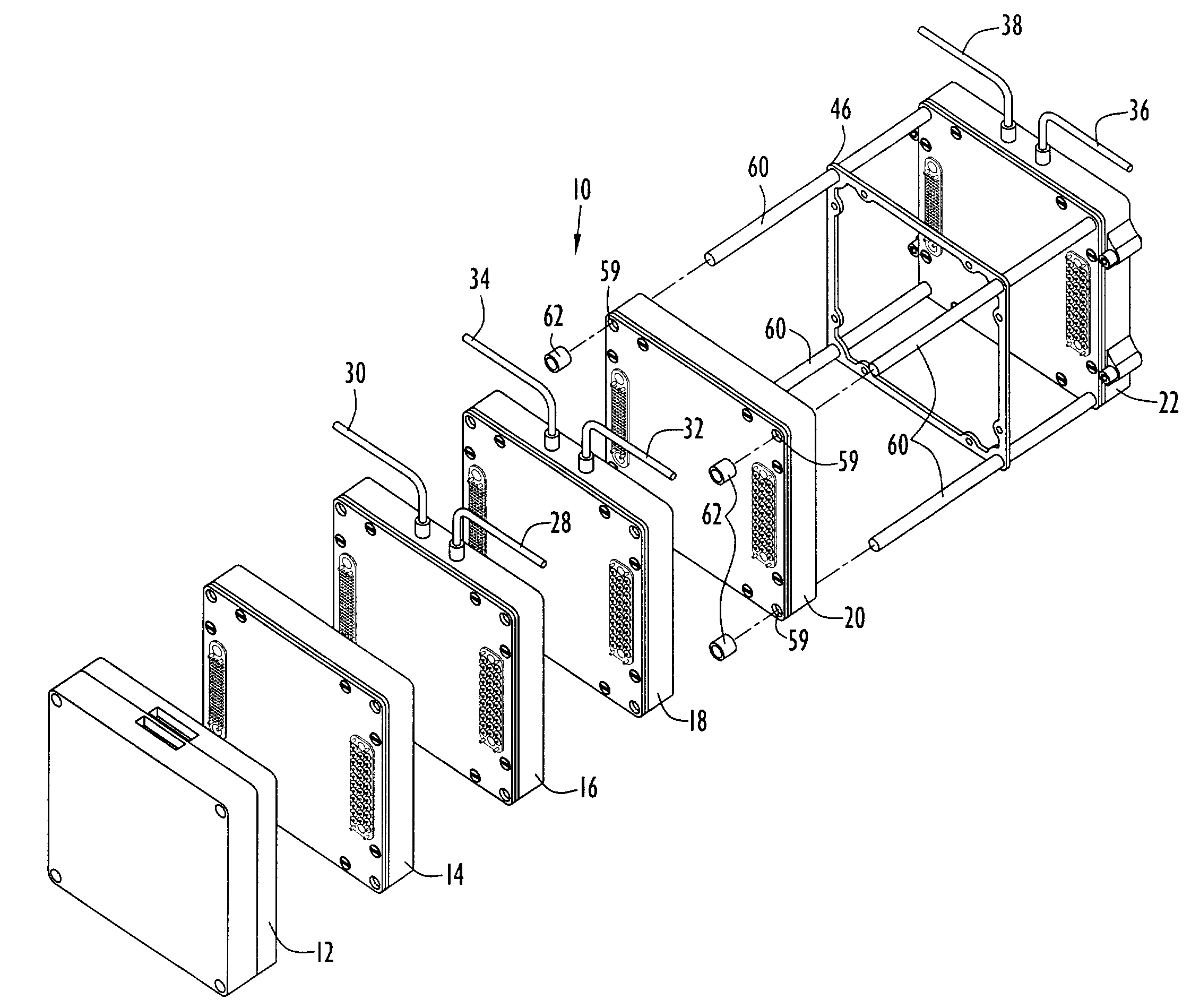
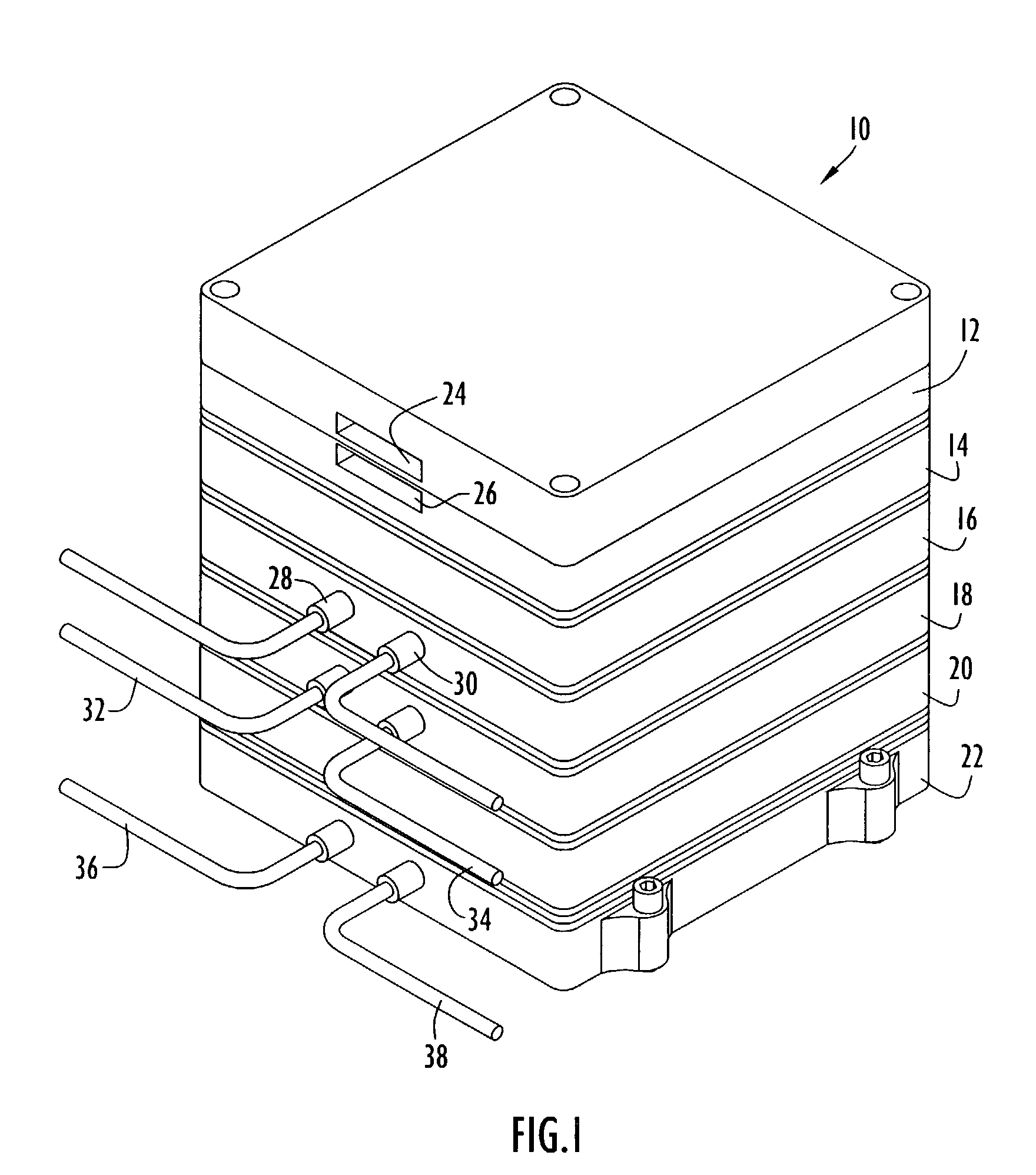
[0029]The disclosed miniature multifunctional integrated terminal is a small, modular, highly configurable terminal capable of integrating many different subsystems, including sensors employed by spacecraft, aircraft, and other observation platforms. The terminal addresses the integration of sensory, communication, navigation, and related functions in a single package suitable for use over a wide range of applications and platforms. The terminal yields significant benefits by using a common modular technology that readily scales across various missions and reduces cost and risk to any one mission. By using common processors for sensory, communication and navigation processing, the number of distinct subsystems aboard a platform can be decreased, fusing these functions into a single miniature package. The resulting terminal is designed to be highly scalable and remotely programmable to meet mission specific needs while reducing size, weight, power and cost.

[0030]Referring to FIG. 1, ...


PUM


Abstract

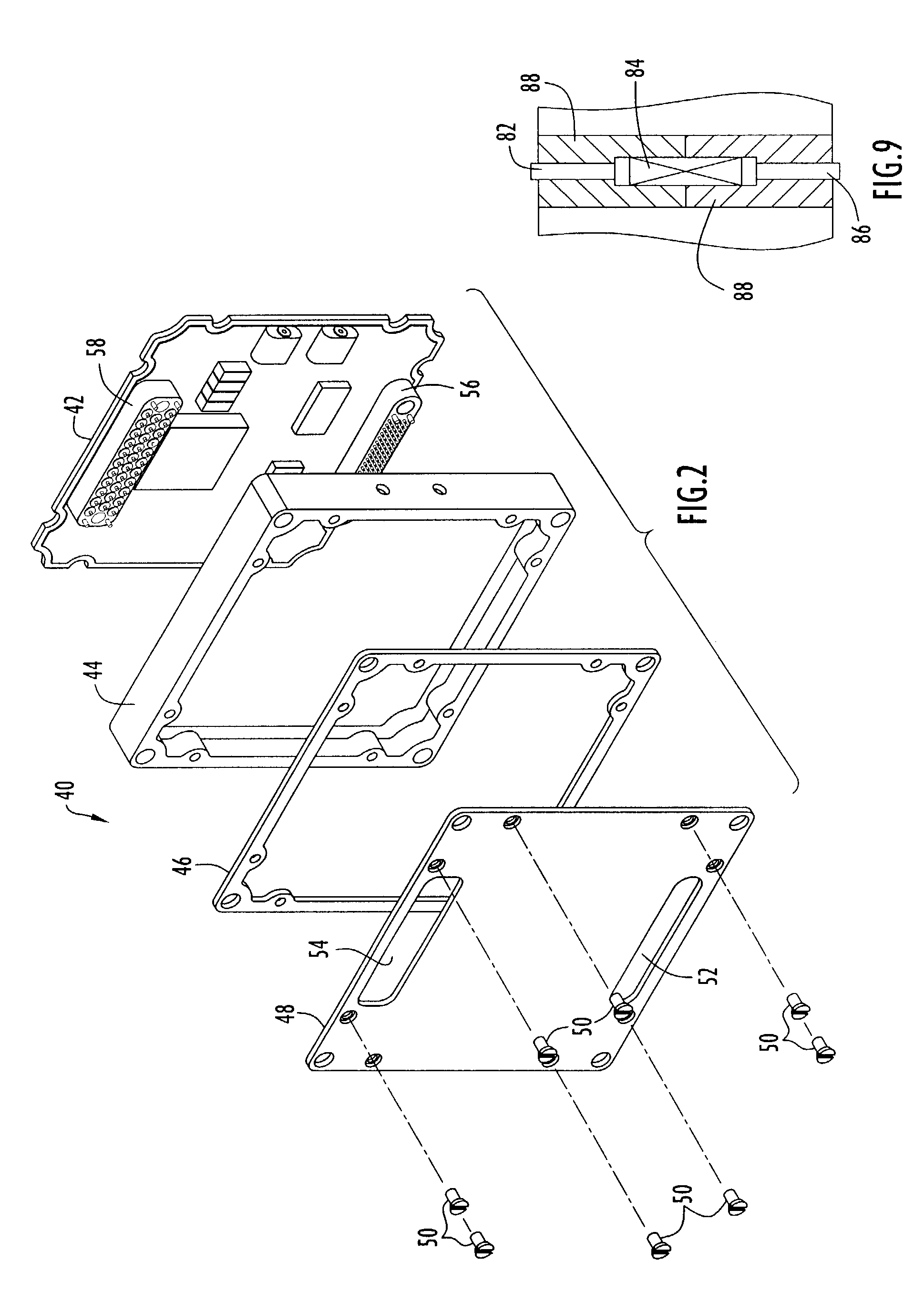
A miniature, multimode, modular RF terminal includes a plurality of processing modules, where at least one of the processing modules includes an external connector for conveying an input or output RF signal. The terminal further includes a segmented coaxial analog bus comprising a plurality of multi-conductor coaxial connectors, wherein each of the multi-conductor coaxial connectors is integrated in or forms a portion of one of the processing modules, and wherein the segmented coaxial analog bus conveys RF signals between the processing module having the external connector and at least one other processing module. The modules of the terminal can be arranged in a stack, on a rigid substrate, connected via a flexible substrate or combinations thereof. The terminal supports processing of communication, navigation and sensor signals.

Description

CROSS REFERENCE TO RELATED APPLICATION[0001]This application claims priority from U.S. Provisional Patent Application Ser. No. 60 / 369,837 entitled “Miniature Multifunctional Integrated Terminal,” filed Apr. 5, 2002. The disclosure of this provisional patent application is incorporated herein by reference in its entirety.BACKGROUND OF THE INVENTION[0002]1. Field of the Invention[0003]The present invention relates to a modular RF terminal and, more particularly, to a miniature terminal including discrete, reconfigurable modules interconnected by high-density analog and digital busses for distributing communication, navigation, sensing and control data among the modules.[0004]2. Description of the Related Art[0005]In digital devices that generate and process RF signals, such as modern transceivers, it is beneficial to minimize the size, weight, power consumption and cost. For example, such goals are required for the equipment to be used in the Earth Science Enterprise (ESE) mission thr...

Claims


Application Information

Patent Timeline
IPC IPC(8): H05K7/10
CPCH05K7/023H01R24/40
Inventor HARLACHER, MARC A.CUNNINGHAM, KENNETH D.
Owner HARRIS CORP
Learn More