Component specific machine wear determination with x-ray fluorescence spectrometry

a technology of x-ray fluorescence spectrometry and component specific machine, which is applied in the field of component specific machine wear determination by analysis of lu, can solve the problems of increasing the chance of machine failure during use, requiring ongoing maintenance, and too frequent preventative maintenan

Inactive Publication Date: 2007-02-27
BATTELLE MEMORIAL INST
View PDF32 Cites 23 Cited by
  • Summary
  • Abstract
  • Description
  • Claims
  • Application Information

AI Technical Summary

Problems solved by technology

Machines perform a variety of valuable functions in industry, but they require ongoing maintenance.
However, too frequent preventative maintenance is costly, in terms of labor, materials and the loss of use during the needed machine down time.
Conversely, increasing the preventative maintenance intervals increases the chance a machine will fail during use, which itself can be costly as well as dangerous and inconvenient.
Furthermore, some failures, such as where a component malfunctions due to damage, an inherent defect, improper installation, etc. are often unpredictable and therefore are difficult to head off with preventative maintenance performed solely on a calendar based or use based schedule.
For example, when the moving parts of a machine experience wear, fine particles are typically dispersed into the machine's lubricating fluid.
However, the simple quantification of fine particles in the lubricating fluid is a non-specific indication of wear.
As a result, particle count measurements can fail to capture the true state of the machine, and this potential for error increases as the number of wearing parts increases.
Accordingly, a situation could arise where one of these bearing wears at an abnormally high rate, putting the engine at risk of failure.
However, the remaining bearings could wear at sufficiently low rates that the overall quantity of wear material in the lubricating fluid of the bearings does not indicate any impending failure.
Unfortunately, the ability to detect such a condition or to otherwise provide component-specific wear information in machines is limited.

Method used


Image

  • Component specific machine wear determination with x-ray fluorescence spectrometry
  • Component specific machine wear determination with x-ray fluorescence spectrometry
  • Component specific machine wear determination with x-ray fluorescence spectrometry

Examples


Embodiment Construction

[0012]For the purposes of promoting an understanding of the principles of the invention, reference will now be made to the embodiments illustrated in the drawings and specific language will be used to describe the same, where like reference numerals are used to describe like structures. Nevertheless, as it is the claims that define the invention, it is to be understood that no limitation of the scope of the invention is intended by any specific language used to describe the illustrated embodiments. Alterations and further modifications in the illustrated embodiments and further applications of the principles of the invention are contemplated as would normally occur to one skilled in the art to which the invention relates.

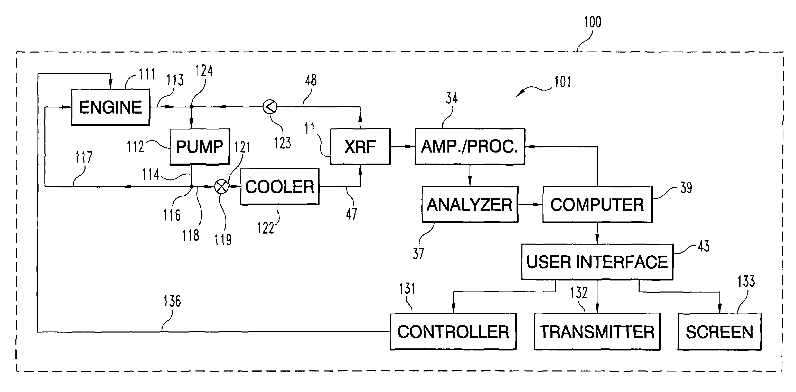
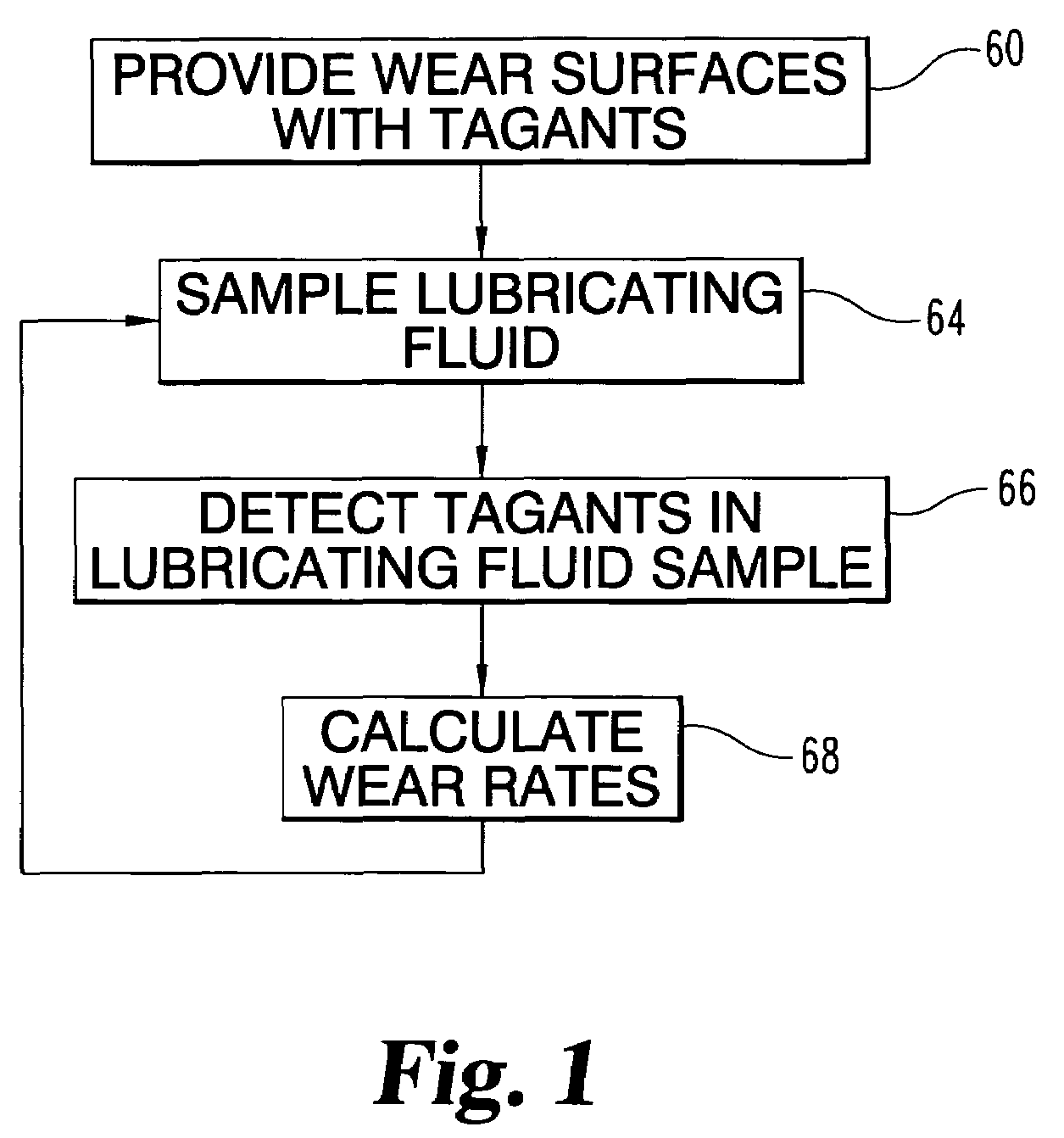
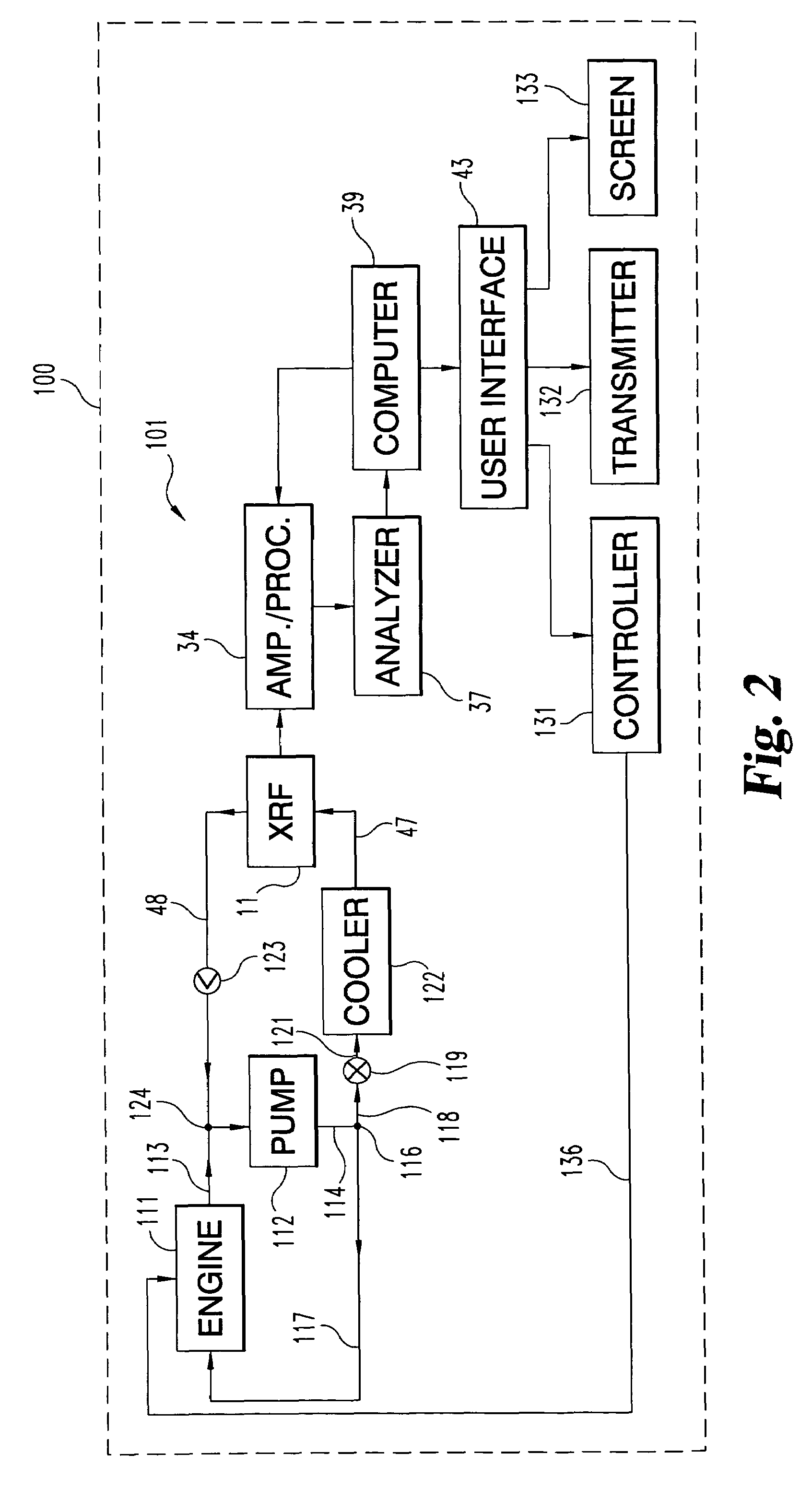
[0013]Briefly, in one aspect the present invention provides for the determination of machine component wear through the detection of tagants in a lubricating fluid. Tagants are material that has been provided in signature amounts in each of the wear surfaces of the ...


PUM

PropertyMeasurementUnit
atomic numberaaaaaaaaaa
fluorescenceaaaaaaaaaa

Abstract

X-ray fluorescence analysis is used to determine wear of machine parts on a component-specific basis. The individual wetted wear surfaces of the machine are provided with a signature tagant composition, and as the components wear, the amounts of each tagant in the lubricating fluid are determined by the x-ray fluorescence analysis. An analysis system tracks the amounts of the tagants in the lubricating fluid, and with information of the signature tagant composition of each wear surface, calculates wear rate information for each of the wear surfaces. This component-specific wear information is then used in scheduling maintenance and predicting failures of the machine.

Description

BACKGROUND[0001]The present invention relates generally to machine wear detection, and more particularly, but not exclusively, to component-specific wear determination by analysis of a lubricating fluid.[0002]Machines perform a variety of valuable functions in industry, but they require ongoing maintenance. Because of the costs associated with performing both preventative and corrective maintenance, significant attention is given to developing and implementing efficient maintenance programs. The general goal of most maintenance programs is to protect the machine and prolong its useful life while minimizing down time and other maintenance expenses.[0003]Some maintenance programs are schedule-based. In these, intervals are established for certain preventative maintenance tasks, such as inspection or replacement of certain components or groups of components, and the task is performed upon the expiration of the interval. However, too frequent preventative maintenance is costly, in terms...

Claims


Application Information

Patent Timeline
Patent Type & Authority Patents(United States)
IPC IPC(8): G01N23/223
CPCG01N23/223G01N33/2888G01N2223/076
Inventor WILSON, BARY
Owner BATTELLE MEMORIAL INST
Why Eureka
Try Eureka