Method and system for monitoring performance of optical network

a technology of optical network and monitoring system, applied in the field of optical network, can solve the problems of insufficient information and limited information for efficient monitoring of optical network performance, and achieve the effect of simplifying the monitoring process and effective and accurate monitoring of the performance of the entire network

Inactive Publication Date: 2007-02-27
ALCATEL LUCENT CANADA +1
View PDF11 Cites 11 Cited by
  • Summary
  • Abstract
  • Description
  • Claims
  • Application Information

AI Technical Summary

Benefits of technology

[0080]The methods and systems for monitoring performance of optical networks described above provide the following advantages. Introduction of network characteristics related to identification tags into wavelength channels and detection of their presence and power levels in the network allows more effective and accurate monitoring of the performance of the entire network. In many situations, when specific identifier information is required, e.g. fiber and / or fiber bundle information, it simplifies the monitoring process by allowing the measurement of a fewer number of parameters. Additionally, it allows discovery of the topology of the network which otherwise would not be possible, e.g. to determine paths of individual channels in the network, traffic load and wavelengths channels traveling through particular fiber and bundle sections and to monitor various scenarios of network failure or changes introduced to the network.

Problems solved by technology

Although the approaches described in the cited prior art provide useful information and identification of different optical signals (wavelengths channels) in a network, their origin and power levels, this information alone is limited and not sufficient for the efficient monitoring of the performance of the optical network.

Method used


Image

  • Method and system for monitoring performance of optical network
  • Method and system for monitoring performance of optical network
  • Method and system for monitoring performance of optical network

Examples


first embodiment

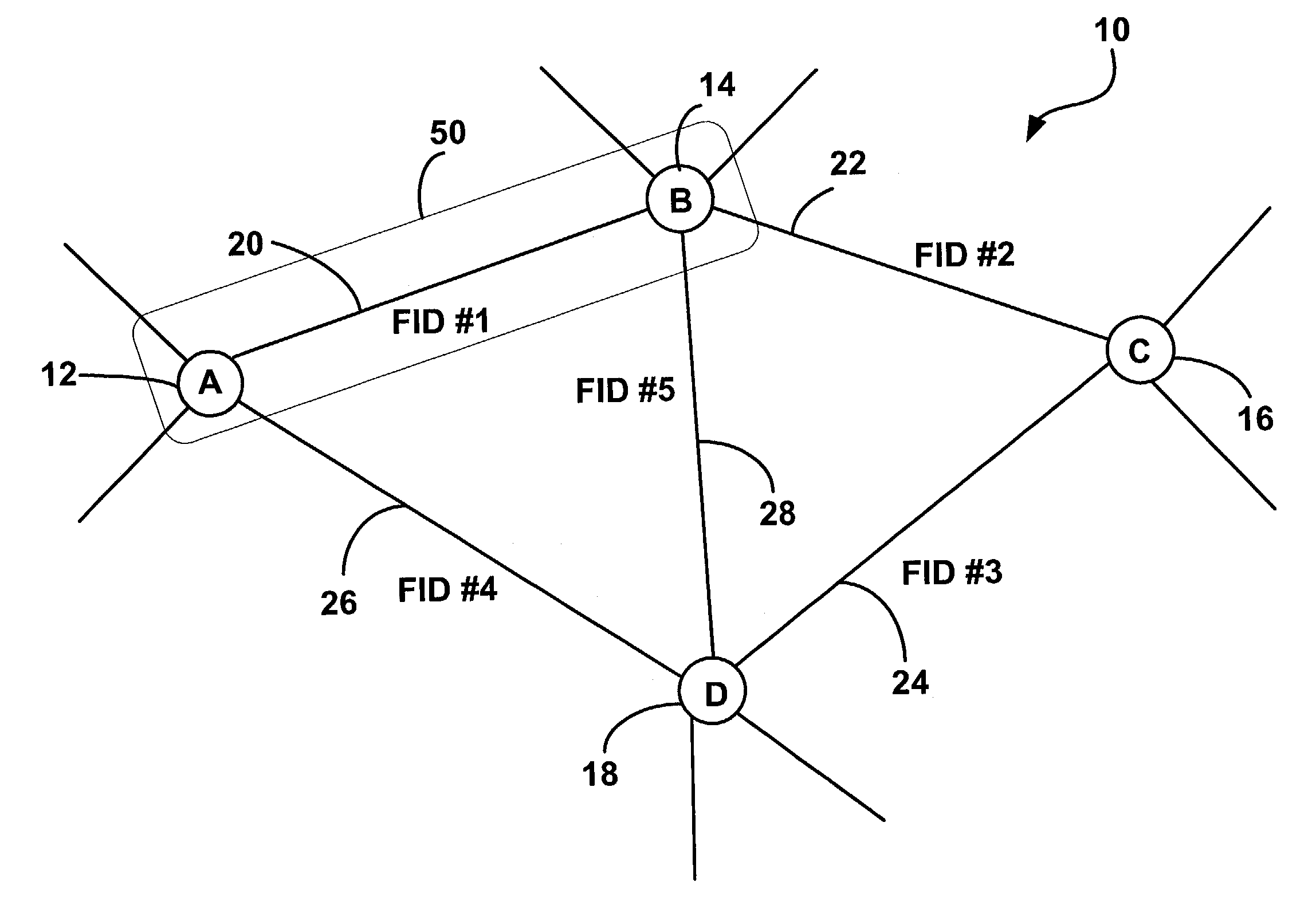
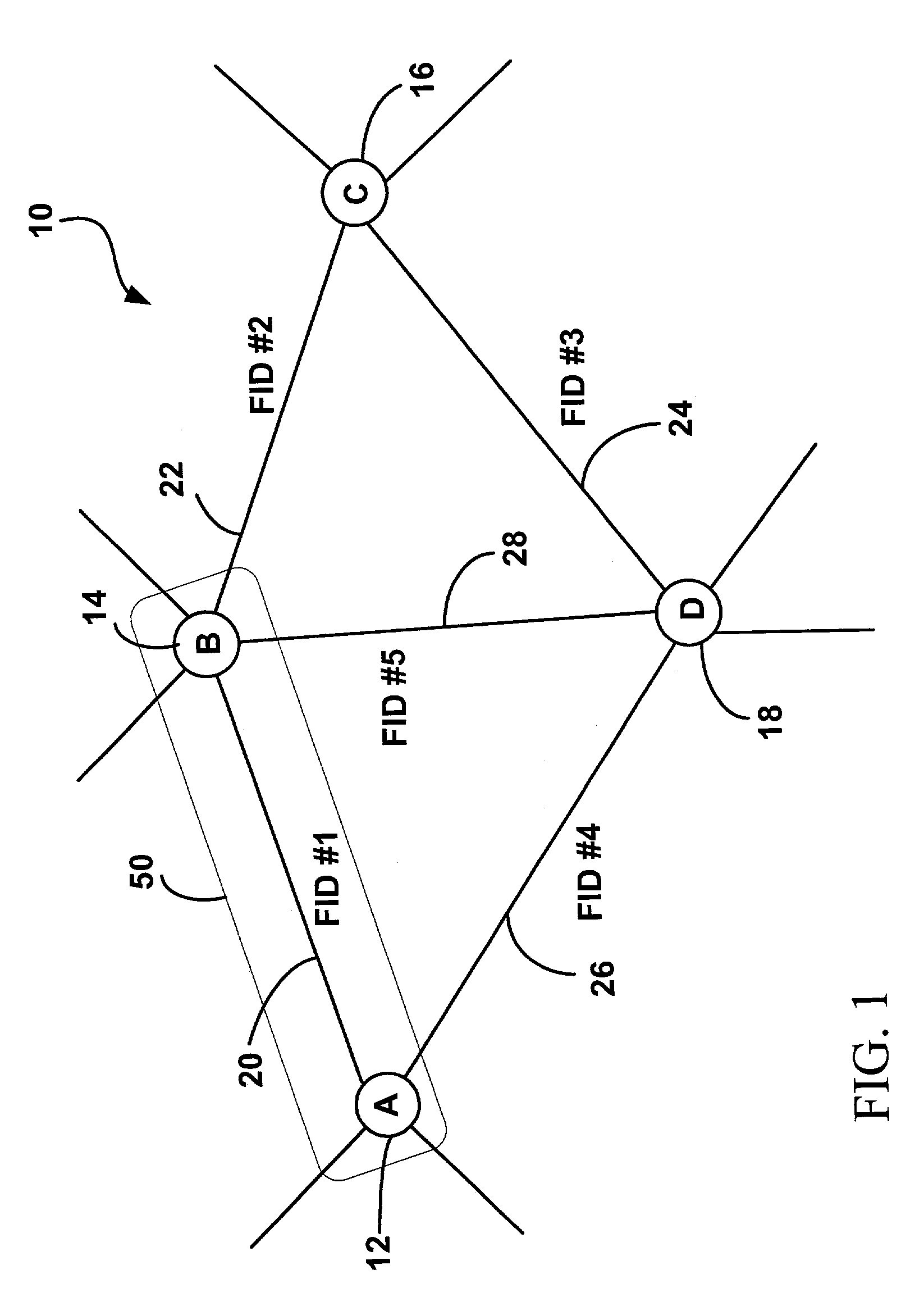
[0089]the invention describes a method and apparatus for monitoring performance of a dense wavelength division multiplexing (DWDM) network by introducing a fiber identification (FID) tone, or fiber identification tag, associated with a section of fiber between the two nodes in the network. The FID tag is encoded onto a group of optical signals (wavelength channels) traveling through the section of the fiber, the tag being unique to the fiber section. Optionally the FID tag may be introduced into all or only selected optical signals traveling through the fiber section.

[0090]By a way of example, FIG. 1 illustrates an optical network 10 having a plurality of network nodes, four of them being shown in FIG. 1 as nodes A, B, C and D and designated by reference numerals 12, 14, 16 and 18 respectively. For the sake of simplicity, each pair of nodes is connected with one fiber section only, thus five fiber sections in total connecting the four nodes of the network 10 and being shown in FIG. ...

second embodiment

[0108]the invention describes a method and apparatus for monitoring performance of a dense wavelength division multiplexing (DWDM) network by introducing a bundle identification (BID) tone, or bundle identification tag, associated with a bundle (cable) of fibers between the two nodes in the network, where each bundle can carry hundreds of individual fibers.

[0109]By a way of example, FIG. 6 illustrates an optical network 300 having a plurality of network nodes, four of them being shown in FIG. 6 as nodes A, B, C and D and designated by reference numerals 212, 214, 216 and 218 respectively. The network 300 of the second embodiment is similar to the network 10 of the first embodiment except for the pairs of nodes now being connected with bundles of fibers, each bundle having more than one fiber section. Five bundle sections 220, 221, 222, 223 and 224 connecting the four nodes of the network 300 are shown in FIG. 6. In more detail, the bundle section 220, including fiber sections 225, 2...


PUM


Abstract

The invention describes methods and systems for monitoring the performance of an optical network by marking a group of optical signals with a set of identification tags which are unique to network characteristics. In the preferred embodiments, fiber identification (FID) and bundle identification (BID) tags are encoded into optical signals by marking an optical signal with low frequency dither tones whose frequencies are unique to the fiber section and to a bundle of fibers respectively. Detecting of the FID and BID tones provides more effective and accurate monitoring of performance of the optical network and allows determining of the network topology, e.g. paths of optical channels and traffic load through different fiber sections in the network. Other sets of hierarchically arranged identifiers encoded into optical signals have also been proposed, including band, conduit, city, region, country, etc. identifiers, as well as identifiers related to network security and service characteristics.

Description

RELATED APPLICATIONS[0001]This patent application is a Continuation-in-Part of the U.S. patent application to Wen Liu et al. entitled “Method and System for Monitoring Performance of Optical Network” Ser. No. 09 / 990,366 filed on Nov. 23, 2001 now U.S. Pat. No. 7,031,606.FIELD OF THE INVENTION[0002]This invention relates to optical networks, and in particular to methods and systems for monitoring performance of optical networks.BACKGROUND OF THE INVENTION[0003]It is a common practice in an optical network to introduce a signal tracking mechanism, which would allow the distinguishing and supervising of individual wavelength channels along the optical path. Commonly the tracking mechanism is implemented by modulation of a wavelength channel with a low frequency dither tone, which is unique to the transmitted channel and remains unchanged as the channel travels through the network. This approach has been described in several articles, patents and patent applications, some of which are l...

Claims


Application Information

Patent Timeline
Patent Type & Authority Patents(United States)
IPC IPC(8): H04B10/08H04B10/02
CPCH04B10/00H04J14/0227H04J14/0264H04J14/0267H04J14/0276H04J14/0258H04B2210/075
Inventor LIU, WENOBEDA, PAUL DAVIDVETHANAYAGAM, NIRANJANOPREA, DAN
Owner ALCATEL LUCENT CANADA
Why Eureka
Try Eureka