Arithmetic structures for programmable logic devices

a logic device and programmable logic technology, applied in the field of logic elements, can solve the problems of inefficiency of larger luts, more hardware is required to construct the 6-lut logic elements, and the cost and speed of a logic circuit constructed with luts,

Active Publication Date: 2007-02-27
ALTERA CORP
View PDF55 Cites 46 Cited by
  • Summary
  • Abstract
  • Description
  • Claims
  • Application Information

AI Technical Summary

Benefits of technology

[0012]According to some embodiments, arithmetic structures in logic elements result from combining inverters and pass gates (or other multiplexing hardware) with LUT hardware. According to other embodiments, arithmetic structures in logic elements result from combining dedicated adder hardware (e.g., including XOR units) and fracturable LUT hardware. According to other embodiments, arithmetic structures in logic elements result from providing complementary input connections between multiplexers and LUT hardware. In this way, the present invention enables the incorporation of arithmetic structures with LUT structures in a number of ways. The present invention provides flexibility for combining functions in logic elements including various arithmetic functions, relative speeds and costs. In some operational settings, the preferred choice will depend on the typical mix of functions to be implemented in a PLD and the relative importance of speed and area.

Problems solved by technology

While mask programming may have disadvantages relative to some of the field programmable options already listed, it may be useful in certain high volume applications.
There is a tradeoff between cost and speed of a logic circuit constructed with LUTs.
Under these assumptions, more hardware is required to construct the 6-LUT logic elements because the reduced number of LUTs is insufficient to compensate for the larger complexity of each LUT.
One reason for the lack of efficiency of larger LUTs is that not all logic functions will use all K inputs.
However, these examples have typically been limited to simple arithmetic operations (e.g., an addition of two inputs) and have generally not exploited internal LUT structures.

Method used


Image

  • Arithmetic structures for programmable logic devices
  • Arithmetic structures for programmable logic devices
  • Arithmetic structures for programmable logic devices

Examples


Embodiment Construction

Inverters and Pass Gates

[0032]Arithmetic structures can result from combining inverters and pass gates (or other multiplexing hardware) with LUT hardware in a logic element.

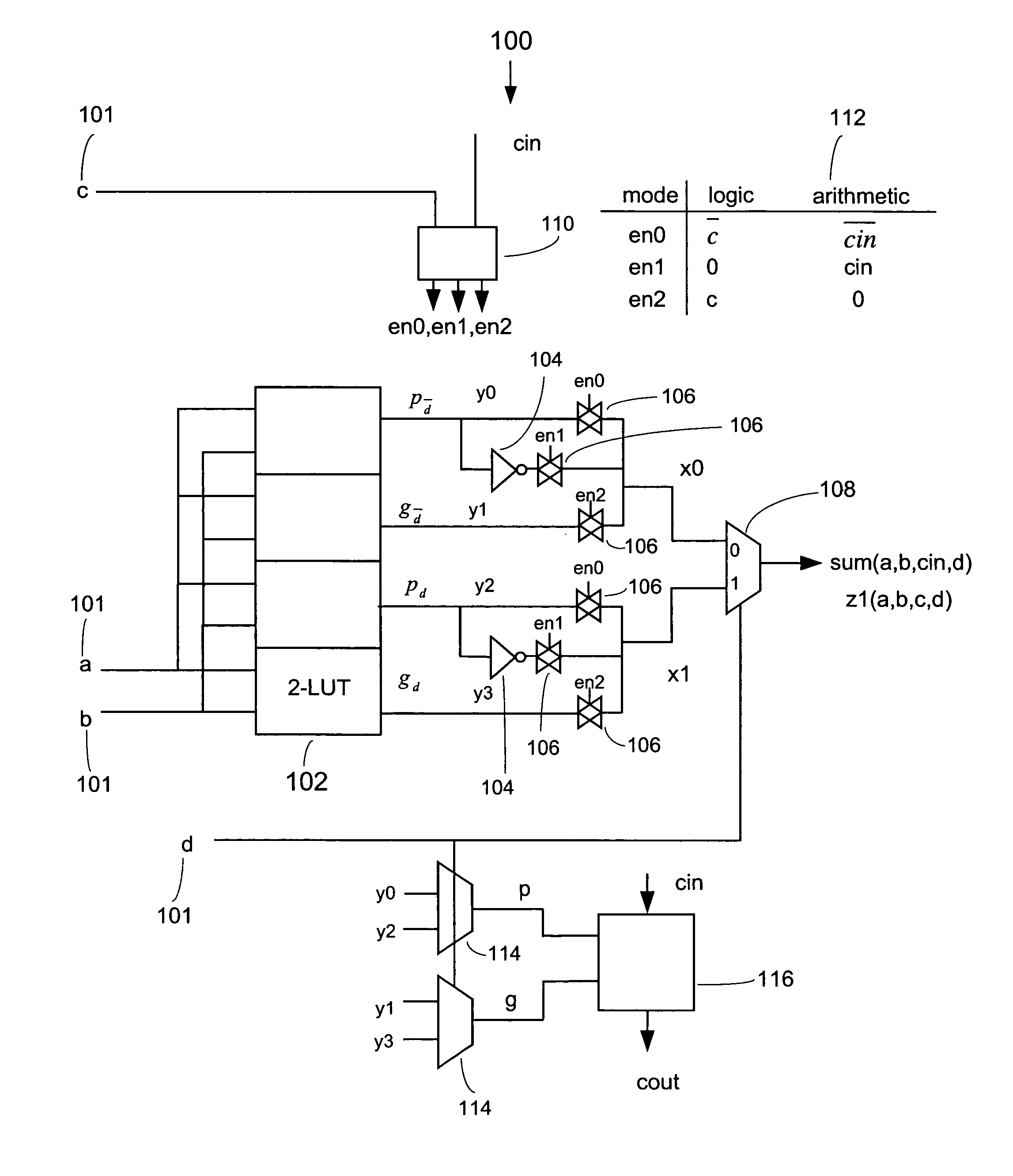
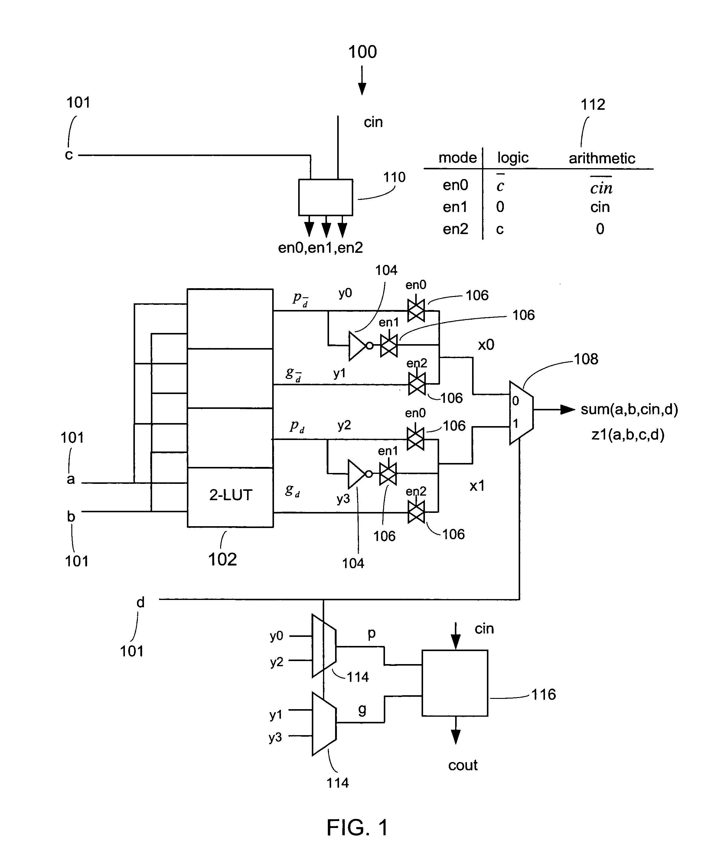
[0033]FIG. 1 shows a logic element (LE) 100 according to an embodiment of the present invention where a single 4-LUT is broken down into (or considered as) four 2-LUTs. The logic element 100 includes four control inputs (or controls) 101 denoted as a, b, c, and d. Four 2-LUTs 102 are connected to two inverters 104 and six pass gates 106. The four 2-LUTs 102 provide four output values, y0, y1, y2, and y3, and the six pass gates 106 are arranged to provide two output values, x0 and x1. An output multiplexer 108 receives input from the pass gates 106 and produces one of two different outputs depending on the mode of operation: an arithmetic mode and a logic mode.

[0034]The pass gates 106 are controlled by pass gate controls e0, e1, and e2 so that when a pass gate control is zero the signal does not pass and when a pa...


PUM


Abstract

According to some embodiments, arithmetic structures in logic elements result from combining inverters and pass gates (or other multiplexing hardware) with LUT hardware. According to other embodiments, arithmetic structures in logic elements result from combining dedicated adder hardware (e.g., including XOR units) and fracturable LUT hardware. According to other embodiments, arithmetic structures in logic elements result from providing complementary input connections between multiplexers and LUT hardware. In this way, the present invention enables the incorporation of arithmetic structures with LUT structures in a number of ways.

Description

BACKGROUND OF THE INVENTION[0001]1. Field of Invention[0002]The present invention relates to logic elements for use with programmable logic devices or other similar devices.[0003]2. Description of Related Art[0004]Programmable logic devices (PLDs) (also sometimes referred to as CPLDs, PALs, PLAs, FPLAs, EPLDs, EEPLDs, LCAs, FPGAs, or by other names), are well-known integrated circuits that provide the advantages of fixed integrated circuits with the flexibility of custom integrated circuits. Such devices are well known in the art and typically provide an “off the shelf” device having at least a portion that can be electrically programmed to meet a user's specific needs. Application specific integrated circuits (ASICs) have traditionally been fixed integrated circuits, however, it is possible to provide an ASIC that has a portion or portions that are programmable; thus, it is possible for an integrated circuit device to have qualities of both an ASIC and a PLD. The term PLD as used h...

Claims


Application Information

Patent Timeline
Patent Type & Authority Patents(United States)
IPC IPC(8): G06F7/38
CPCG06F7/501G06F2207/4816
Inventor LEWIS, DAVIDPEDERSEN, BRUCEKAPTANOGLU, SINAN
Owner ALTERA CORP
Why Eureka
Try Eureka