Unlock instant, AI-driven research and patent intelligence for your innovation.

Measurement circuit and method for serially merging single-ended signals to analyze them

a measurement circuit and signal technology, applied in the field of signal measurement, can solve the problems of inability to easily carry out signal test using the eye diagram of single-ended signals, inability to carry out test analysis in an environment, and inability to simultaneously show single-ended signals for full speed mode tests on a display

Inactive Publication Date: 2007-02-27
SAMSUNG ELECTRONICS CO LTD
View PDF7 Cites 3 Cited by
  • Summary
  • Abstract
  • Description
  • Claims
  • Application Information

AI Technical Summary

Benefits of technology

The present invention provides a measurement circuit and method for analyzing signals from a device under test (DUT) using a technique called serially merging. This allows for the analysis of single-ended signals even when using an automatic test equipment (ATE). The measurement circuit detects signals from the DUT, divides them into a DC portion and a digital pulse portion, and stores them in memory. The signals are then serially merged, analyzed, and stored again in memory. The analysis data includes information about the signals, such as eye diagram data and statistics about the crossover voltage and rising / falling time of the signals. The technical effect of this invention is to provide a more accurate and reliable method for analyzing signals from the DUT.

Problems solved by technology

When a semiconductor device such as the USB 2.0 is manufactured, “compliance tests” with respect to only some standardized items including a receiving function, transmission jitter, crossover voltage, rising time and falling time are carried out due to various difficulties in tests.
However, the test analysis cannot be carried out in an environment where the test is executed by automated test equipment (ATE).
In this case, however, single-ended signals for a full speed mode test cannot be simultaneously shown on a display.
Accordingly, a signal test using the eye diagram of the single-ended signals cannot be easily carried out.

Method used


Image

  • Measurement circuit and method for serially merging single-ended signals to analyze them
  • Measurement circuit and method for serially merging single-ended signals to analyze them
  • Measurement circuit and method for serially merging single-ended signals to analyze them

Examples


Embodiment Construction

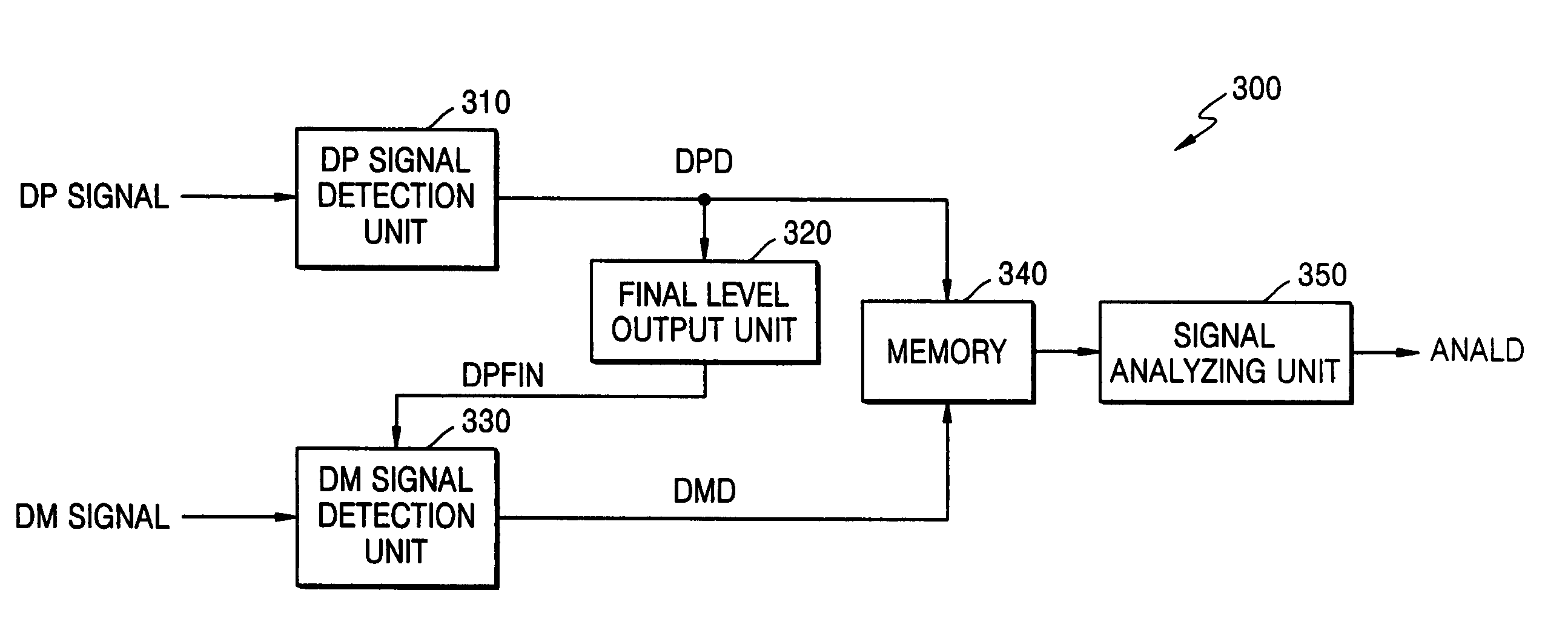
[0034]FIG. 3 is a block diagram of a measurement circuit 300 according to an embodiment of the present invention. Referring to FIG. 3, the measurement circuit 300 includes a DP signal detection unit 310, a final level output unit 320, a DM signal detection unit 330, a memory 340, and a signal analyzing unit 350.

[0035]As described above, differential signals used in a high-speed serial data interface include a DP signal and a DM signal. When a transmitting system transmits transmission data in the form of the differential signals, a receiving system extracts the transmission data from a signal obtained by subtracting the DM signal from the DP signal. The measurement circuit 300 according to the present invention is used in probing single-ended signals with respect to the DP and DM signals in a full speed mode for transmitting 12 MHz data in a semiconductor device such as a USB 2.0 device to analyze the single-ended signals. That is, when automated test equipment (ATE) is used, since ...


PUM


Abstract

Provided are a measurement circuit and method for serially merging single-ended signals to analyze them. To analyze two differential signals probed from a DUT, that is, DP and DM signals, the measurement circuit detects DP data from which its DC portion has been removed and DM data from which its DC portion has been removed, stores the two data signals in a memory, and then serially merges the two data signals stored in the memory without distorting them. The measurement circuit divides the serially merged signal at a predetermined period and overlaps the divided signals to generate eye diagram data and analysis data including crossover voltages, rising time, falling time and so on.

Description

BACKGROUND OF THE INVENTION[0001]This application claims the priority of Korean Patent Application No. 2004-22887, filed on Apr. 2, 2004, in the Korean Intellectual Property Office, the contents of which are incorporated herein in their entirety by reference.[0002]1. Field of the Invention[0003]The present invention relates to signal measurement and, more particularly, a measurement circuit and method for analyzing differential signals generated by a semiconductor device or system.[0004]2. Description of the Related Art[0005]Recently, a high-speed serial data interface has become a standard data interface in mobile application products. Through the high-speed serial data interface, serial data composed of differential signals are transmitted between a personal computer and a liquid crystal display monitor or between a personal computer and a universal serial bus (USB) 2.0 at a high transmission rate. The differential signals used in the high-speed serial data interface include a dif...

Claims


Application Information

Patent Timeline
Patent Type & Authority Patents(United States)
IPC IPC(8): G01R31/28G01R31/319G01R31/00G06F11/00G06F11/30G08C25/00H03M13/00H04B1/66H04L1/00H04L1/20H04N7/12H04N11/02H04N11/04
CPCH04L1/20A47G9/10A47G9/1072A47G2009/1018
Inventor CHOI, SI-YOUNG
Owner SAMSUNG ELECTRONICS CO LTD