Method and container having reinforcing rib structures

a technology of rib structure and rib structure, which is applied in the field of container manufacturing, can solve the problems of steel and aluminum containers, carries certain concerns about production costs and the quantity of materials used in the fabrication process, and saves production costs, so as to reduce the amount of materials used in construction

Inactive Publication Date: 2007-03-06
WERTH ELMER D +1
View PDF19 Cites 23 Cited by
  • Summary
  • Abstract
  • Description
  • Claims
  • Application Information

AI Technical Summary

Benefits of technology

[0010]It is an object of the present invention to provide a new and useful end closure for a container where the amount of material used in construction is reduced yet where the structural integrity of the container is maintained.
[0011]It is another object of the present invention to provide a container with end closures, either in the form of a lid or an integrally formed bottom wall, that have improved strength.
[0012]It is yet another object of the present invention to provide a can body with a domed end closure of improved configuration for strength that may then be used to form a container.
[0014]Yet a further object of the present invention is to provide for the possible reduction of materials used to form container, can bodies and end closures for such containers.

Problems solved by technology

The rising demand for steel and aluminum containers, though, carries certain concerns about production costs and the quantity of material used in the fabrication process.
This saves in the costs of production in two ways.
Nonetheless, the reduction in wall thickness of containers is not without its problems.

Method used


Image

  • Method and container having reinforcing rib structures
  • Method and container having reinforcing rib structures
  • Method and container having reinforcing rib structures

Examples


second embodiment

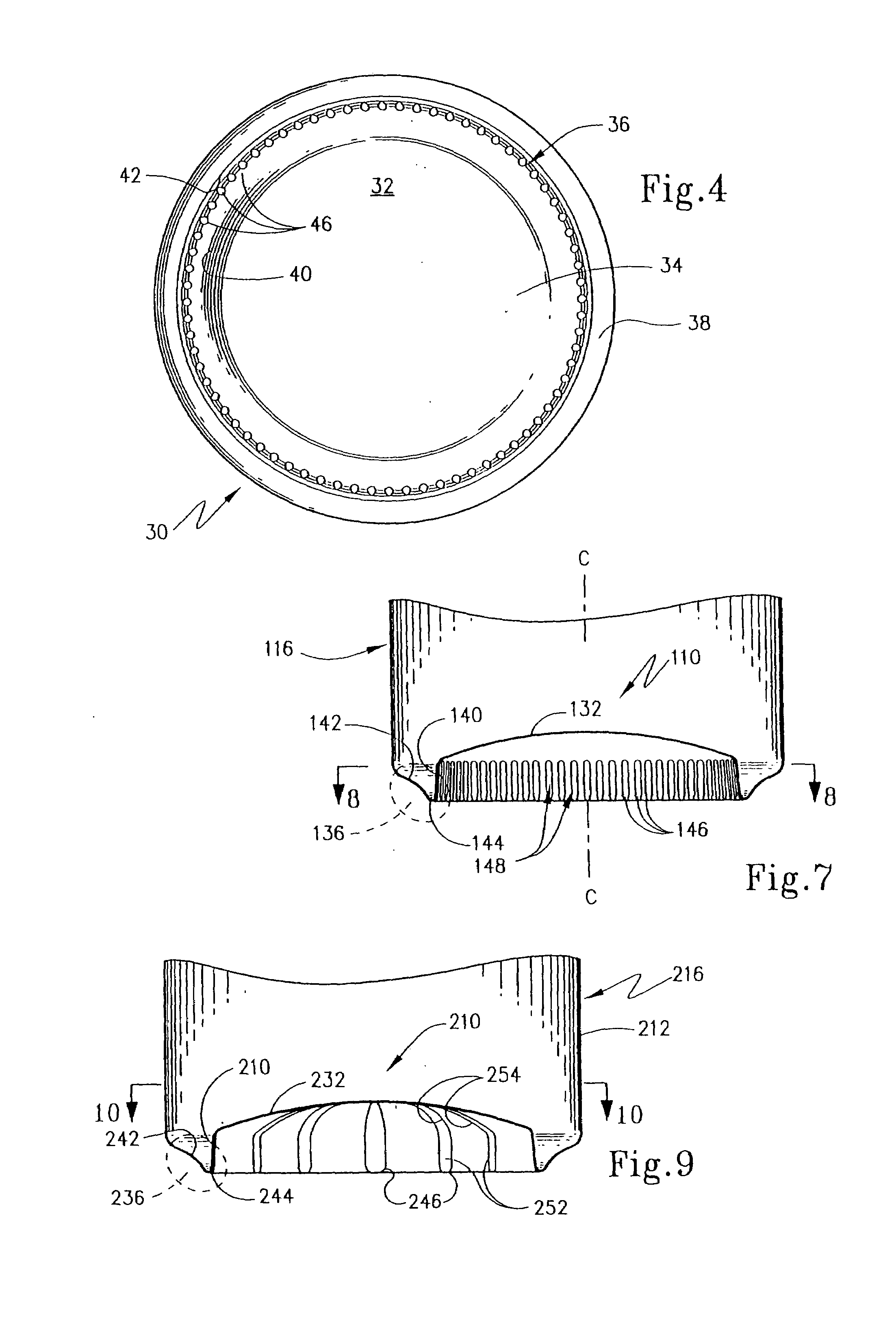
[0048]Turning to FIGS. 7 and 8, an end closure according to the present invention is shown. Here, can body 116 has an end closure in the form of a domed bottom 110 that includes a dome-shaped central body panel 132 that extends transversely of central axis “C”. Domed bottom 110 provides an end closure that is opposite the end where the lid, such as lid 26 or 30, is seamed onto the container. Central body panel 132 has an outer surrounding margin portion 136 that is generally U-shaped in configuration and includes an inner wall portion 140 that is oriented generally parallel to axis “C” and that is joined to an outer wall portion 142 by connecting wall 144. Walls 140 and 142 again provide a support section that is oriented longitudinally relative to the container body and a plurality of rib structures 146 are again provided. Here, wall portions 140, 142 and 144 along with central body panel 136 are formed integrally with side wall 112 of can body 116 as an integral, one-piece constru...

third embodiment

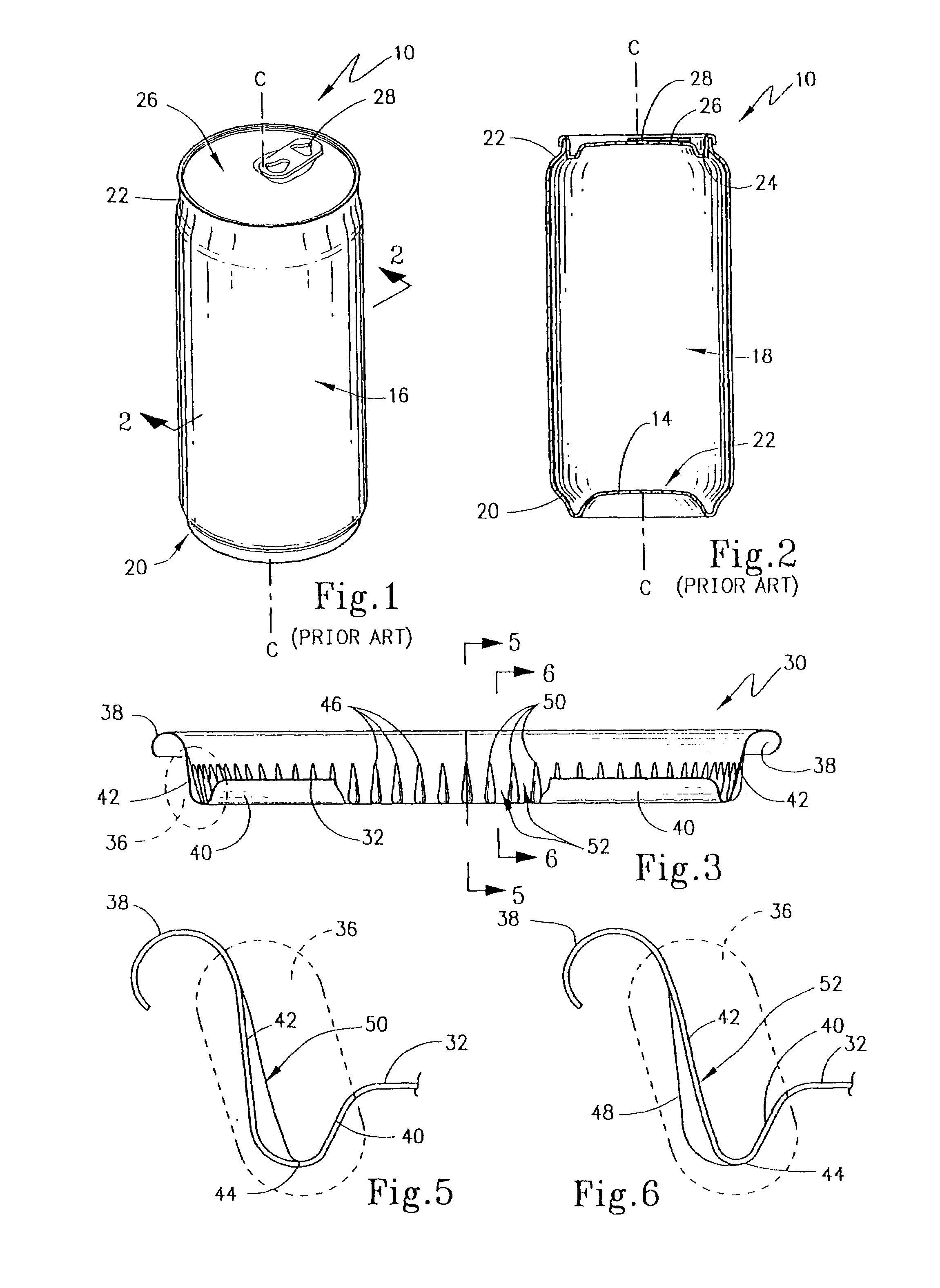
[0049]the present invention is shown in FIGS. 9 and 10. Here, can body 216 has a side wall 212 to which a domed end closure 210 is formed integrally as a one-piece construction therewith. To this end, domed end closure has a central body panel 232 that has an outer margin portion 236 that includes an inner wall portion 240 joined to an outer wall portion 242 by means of a connecting wall 244 to form a generally U-shaped profile. A plurality of rib structures 246 are again equidistantly and equiangularly spaced around dome end closure 210. To this end, rib structures 246 have first rib components 252 that are formed in inner wall portion 240 with second rib components 254 extending onto central body panel portion 232.

fourth embodiment

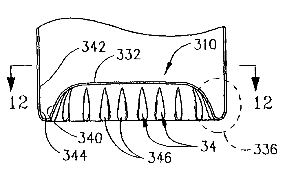
[0050]the present invention is shown in FIGS. 11 and 12. With reference to these Figures, then, it may be seen that a can body 316 has a side wall 312 which has a rectangular (in this instance square) in cross-section. Can body 316 has a domed end closure 310 including a central body 332. Outer margin portion 336 is formed by an inner wall portion 340 joined to an outer wall portion 342 by means of a connecting wall 344 in a manner similar to that described with respect to FIGS. 7–10. Here, inner wall portion 340 is a truncated pyramid and is provided with a plurality of rib structures 346 formed as tear-dropped depressions 348 formed in inner wall 340. Depressions 348 again form troughs 350 that are separated by ridges 352. A structure shown in FIGS. 11 and 12 is to illustrate that the can body according to the present invention as well as the resulting container can have a different geometric cross-section than the cylindrical cross-section shown in FIGS. 1–10. Here, again, centra...


PUM

PropertyMeasurementUnit
geometric shapeaaaaaaaaaa
geometric shapesaaaaaaaaaa
diameteraaaaaaaaaa

Abstract

A method is provided for forming an end closure for a surrounding sidewall of a container, such as an aluminum can. The method includes forming a central body panel oriented transversely to the central axis of the can and forming an outer surrounding margin portion joined to the sidewall such that the margin portion has a support section oriented longitudinally relative to the sidewall. A portion of the margin is corrugated to provide a rib structure having longitudinally extending first rib components located on the support section. This method can be accomplished during the ironing and doming of a can.

Description

[0001]This application is a division of Ser. No. 09 / 981,773 filed Oct. 16, 2001, now U.S. Pat. No. 6,736,284.FIELD OF THE INVENTION[0002]The present invention broadly relates to the manufacture of containers, especially drawn and ironed containers made of steel or aluminum, such as those used in the food and beverage industry. More particularly, the present invention concerns the formation of a margin profile for an end closure that includes reinforcing rib structures. The invention concerns both container lids and can bodies including integral domed end closures.BACKGROUND OF THE INVENTION[0003]The need for packaging of food and beverage products for storage and sale has increased with the increase in human populations and as urbanization has intensified. In addition, the demand for convenient, ready-to-eat products have added to the demand for suitable packaging. A long standing technique for packaging certain foods and beverages is metal cans. Such cans take a variety of geometri...

Claims


Application Information

Patent Timeline
Patent Type & Authority Patents(United States)
IPC IPC(8): B21D51/26B21D51/44B65D6/28B65D6/30B65D8/04B65D8/06B65D8/08B65D8/12
CPCB65D17/08B65D7/46
Inventor WERTH, ELMER D.HAHN, ROGER A.
Owner WERTH ELMER D
Why Eureka
Try Eureka