Low-construction trolley for wire rope hoist

a technology of low-construction trolleys and hoists, which is applied in the direction of trolleys, hoisting equipment, load-engaging elements, etc., can solve the problems of harmful vibration, increased construction costs, and increased construction costs, so as to achieve optimal manufacturing costs, reduce construction costs, and reduce construction costs

Active Publication Date: 2021-03-30
KONECRANES GLOBAL
View PDF22 Cites 3 Cited by
  • Summary
  • Abstract
  • Description
  • Claims
  • Application Information

AI Technical Summary

Benefits of technology

[0007]The invention is thus based on an idea to use a relatively heavy hoisting motor to replace entirely counterweights and spring supports used before, or to at least reduce the need for compensation for masses.
[0011]The invention provides a sufficiently uniform bearing contact of the bearing wheels at the flange of the supporting beam or rail, whereby the wear on the bearing wheels is even and the trolley, and thus the hoist, travel without jerking both with and without a load. The structure has a minimum number of components, so the amount of material used and the manufacturing costs are optimal. At the same time, assembly and maintenance are simpler and cost less. Compared with the prior art, a lighter hoist is easier to mount to overhead structures because it is now possible to dispose of the counterweight, for example.

Problems solved by technology

Due to this, there is an imbalance between the opposite sides of the main support, and thus a counterweight is typically used in an attempt to compensate for it.
The imbalance is harmful because when the trolley is driven without a load, the friction force of the driving bearing wheels may remain too low and cause the wheels to slip.
Disadvantages of prior art solutions for balancing the trolley are, in particular, that the trolley becomes heavier and its structure more complicated.
Moreover, some of these solutions do not necessarily fully solve the problem of imbalance.
Instead, as the structure becomes more complex, other disadvantages appear, for example increase in costs and in the need for maintenance of the trolley.
Additional parts also restrict the positioning of the different trolley components, or make it difficult.

Method used


Image

  • Low-construction trolley for wire rope hoist
  • Low-construction trolley for wire rope hoist
  • Low-construction trolley for wire rope hoist

Examples


Embodiment Construction

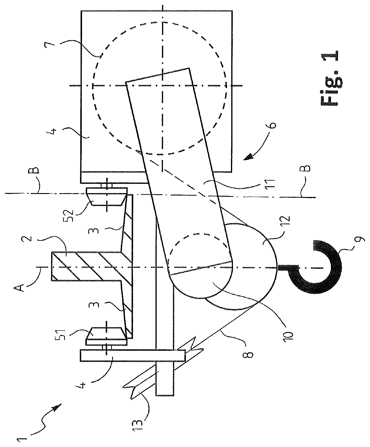
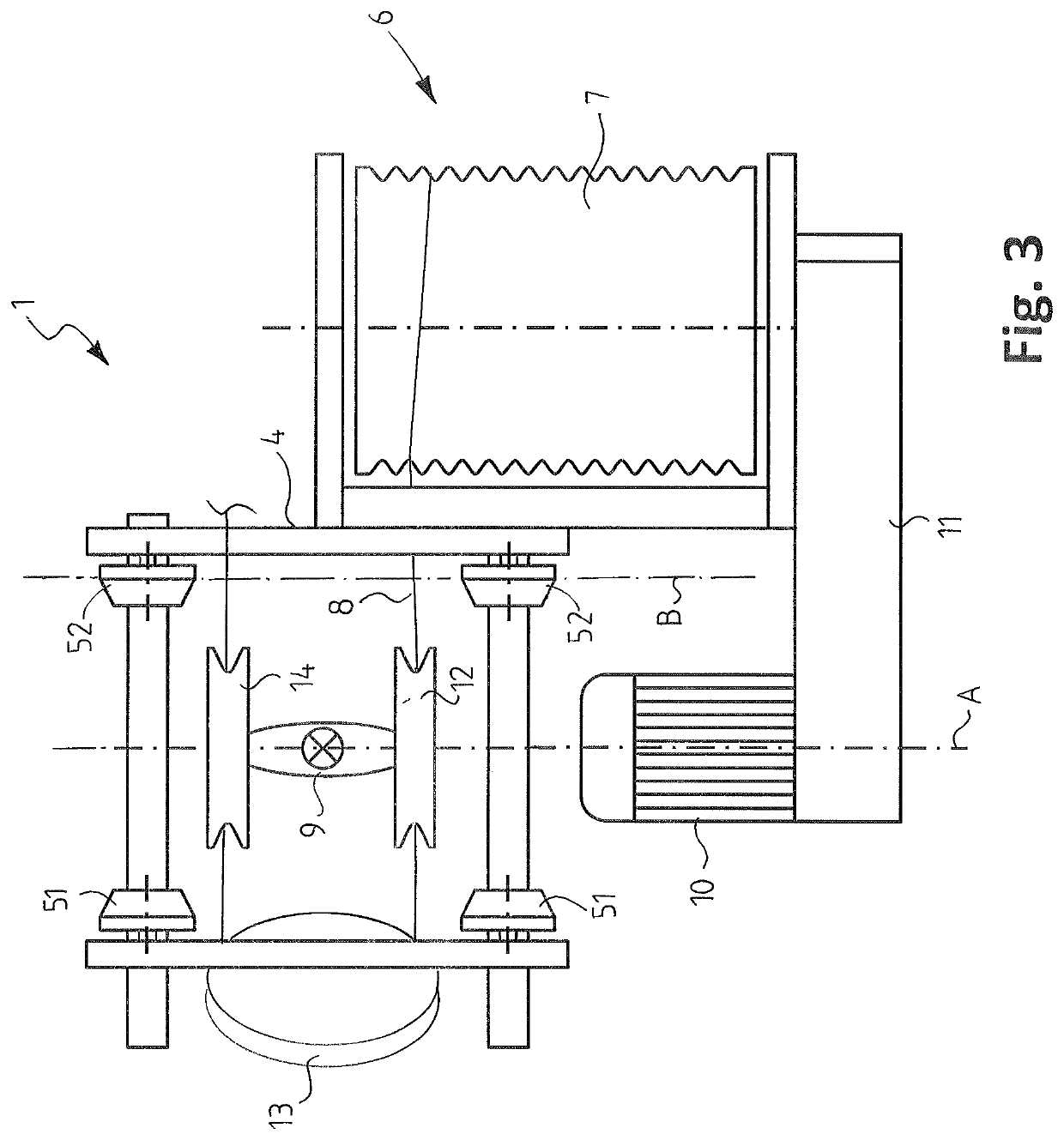
[0018]With reference to FIGS. 1 to 3, a low construction trolley 1 of a wire rope hoist according to the invention is shown, the trolley being arranged to move along a lower flange 3 of a horizontal beam or, as in here, rail 2. The rail 2 typically forms a main support of a bridge crane, or is included in it as its lower part.

[0019]The trolley 1 is shown as a simplified schematic view that only presents what is needed to understand the invention.

[0020]The trolley 1 comprises a trolley frame 4, bearing wheels 51 and 52 and a hoisting mechanism 6.

[0021]The bearing wheels 51 and 52 are fastened to the frame 4 of the trolley and arranged to travel on the upper surface of the lower flange 3 of the rail 2, on both longitudinal edges thereof, and at least some of them are driven wheels to move the trolley 1. An actuator (a moving mechanism of the trolley) for driving the bearing wheels 51 and 52 is not shown.

[0022]The hoisting mechanism 6 comprises a rope drum 7 for a hoisting rope 8, a ho...


PUM


Abstract

A low-construction trolley for a wire rope hoist is arranged to travel along a lower flange of a horizontal rail, on both longitudinal edges thereof. The trolley includes a trolley frame; bearing wheels that are attached to the trolley frame and arranged to travel on an upper surface of the lower flange of the rail; a hoisting mechanism including a rope drum for a hoisting rope, a hoisting member in cooperation with the hoisting rope for hoisting a load, a hoisting motor for driving the rope drum, and a gear to interconnect the hoisting motor and the rope drum; whereby the rope drum is supported to one side of the trolley frame and the hoisting member is arranged to travel under the rail in a vertical plane (A) passing substantially through the middle of the beam. For balancing the trolley without using a counterweight, the hoisting motor is placed under the rail and at least partly on a different side than the rope drum in relation to a vertical plane (B) passing through contact lines of the bearing wheels that touch the lower flange of the rail on the rope drum side.

Description

BACKGROUND OF THE INVENTION[0001]The invention relates to a low-construction trolley for a wire rope hoist, arranged to travel along a lower flange of a horizontal beam or rail, whereby the trolley comprises a trolley frame; bearing wheels that are attached to the frame of the trolley and arranged to travel on an upper surface of the lower flange of the beam or rail, on both longitudinal edges thereof, and at least some of which are driven wheels to move the trolley; a hoisting mechanism comprising a rope drum for a hoisting rope, a hoisting member in cooperation with the hoisting rope for hoisting a load, a hoisting motor for driving the rope drum, and a gear to interconnect the hoisting motor and the rope drum, whereby the rope drum is supported to one side of the trolley frame and the hoisting member is arranged to travel under the beam or rail, in a vertical plane passing substantially through the middle of the beam or rail.[0002]A low-construction trolley is a common overhead t...

Claims


Application Information

Patent Timeline
Patent Type & Authority Patents(United States)
IPC IPC(8): B66C11/06B66D1/14B66C19/00B66D1/12B66D1/36
CPCB66C11/06B66D1/12B66D1/14B66D1/36B66C19/00B66C9/02B66C9/14B66C9/08B66C11/16
Inventor LINDBERG, TEPPOKOKKO, HENRI
Owner KONECRANES GLOBAL
Why Eureka
Try Eureka