Body frame component for a motor vehicle and method of producing it

Inactive Publication Date: 2000-12-05
VOLKSWAGEN AG
View PDF20 Cites 16 Cited by
  • Summary
  • Abstract
  • Description
  • Claims
  • Application Information

AI Technical Summary

Benefits of technology

Another object of the invention is to provide a body frame component having as little weight as possible and which has no significant manufacturing tolerances and as few weak points as possible, and a method of producing it which is not excessively time-consuming.
These and other objects of the invention are attained by providing a component having at least one through hole formed in a region of the low load or stress conditions for the purpose of reducing the amount of material in the body frame component. In accordance with the method of the invention for producing a body frame component, at least one through hole is formed in the region of a flat material in which there is a low load or stress condition after the component has been shaped, when the body frame component is mounted in the vehicle, for the purpose of reducing the amount of material in the body frame component. The through hole or holes are formed before the flat material is shaped or while it is being shaped to provide the specific shape of the body frame component.
Because at least one through hole is formed in a region of low load or stress conditions for the purpose of reducing the amount of material in the body frame component, i.e. for the purpose of saving weight, the disadvantages of the prior art described above are avoided. For one thing, the amount of material used for the body frame component can now be reduced in a simple manner in suitable regions, with the result that assembly of the body frame component, which up to now, using the "tailored-blank" method, has been relatively complex because it requires sheet-metal parts of various thickness, is unnecessary. The fact that complex assembly is no longer necessary means not only that better tolerance values can be achieved, but also that welds which were hitherto necessary and which form weak points are also unnecessary. Since it is now possible for a plurality of through holes to be produced before shaping or during shaping, the method of producing a body frame component can also be carried out in a relatively short time.

Problems solved by technology

Furthermore, body frame components of this type having differing wall thicknesses provided in different regions may also be produced by die-casting, which is expensive.
The conventional body frame components which are produced with the aid of the "tailored-blank" methods or by die-casting are not of optimum design, on the one hand, and, on the other hand, the methods of producing them are very expensive.
Experience has shown that the complex body frame components to be produced with the aid of the "tailored-blank" method can only be manufactured at high cost since various metal sheets of differing structure must be used and the appropriate manufacturing tolerances for the body frame component are difficult to maintain during assembly.
Furthermore, the welds in the components not only have to be designed precisely but they also have to absorb the corresponding forces, and welds within the body frame component constitute weak points.
As a result, the entire method for this type of production is extremely time-consuming.
For one thing, the amount of material used for the body frame component can now be reduced in a simple manner in suitable regions, with the result that assembly of the body frame component, which up to now, using the "tailored-blank" method, has been relatively complex because it requires sheet-metal parts of various thickness, is unnecessary.
The fact that complex assembly is no longer necessary means not only that better tolerance values can be achieved, but also that welds which were hitherto necessary and which form weak points are also unnecessary.

Method used


Image

  • Body frame component for a motor vehicle and method of producing it
  • Body frame component for a motor vehicle and method of producing it

Examples


Embodiment Construction

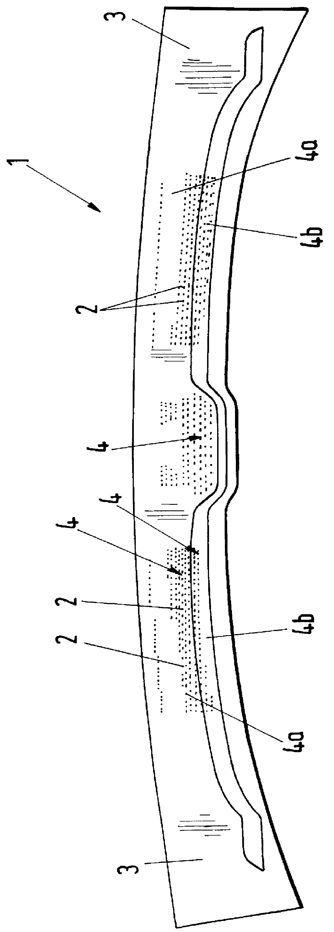
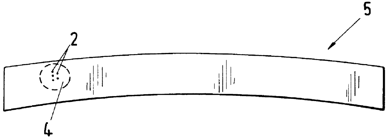
In the typical embodiment of the invention shown in FIG. 1, a body frame component 1 constitutes a member designed in the form of a roof-rack support for a motor vehicle body. The body frame component 1 has a specific shape which is typical for a roof-rack support and is designed so that it absorbs the forces acting on a roof-rack support, that is, when mounted in place, it forms a load-bearing part of the vehicle body. The specific shape of the completed body frame component 1 causes differing load or stress conditions within different regions such as end regions 3, central flat and raised regions 4, intermediate flat regions 4a, and intermediate depressed regions 4b of the body frame component 1 when these forces are being absorbed, i.e. whenever the body frame component 1, which is designed as a roof-rack support, is fitted and used in the roof region of a motor vehicle. As a result there are high load or stress conditions in the first regions 3 of the component, that is in the e...


PUM


Abstract

A body frame component is designed so that it absorbs at least one force acting on it. The specific shape of the body frame component results in differing load or stress conditions within different regions of the body frame component when the force is being absorbed. In particular, high load or stress conditions occur in a first region and low load or stress conditions occur in a second region of the component. A reduction in the weight of the body frame component is achieved by forming at least one through hole in a region of the low load or stress conditions for the purpose of reducing the amount of material in the body frame component. In producing the body frame component, the through hole is formed either before or during the shaping of flat material to produce the specific shape of the body frame component.

Description

BACKGROUND OF INVENTIONThis invention relates to body frame components for motor vehicles which have a specific shape and are designed to absorb a force acting on the component which, because of the specific shape of the body frame component, produces differing load or stress conditions within different regions of the component when the force is being applied, in particular, high load or stress conditions in a first region and low load or stress conditions in a second region.The invention furthermore relates to a method of producing a motor vehicle, which is formed by reshaping an essentially flat material to produce a specific shape which can be fitted within a vehicle body and which, when fitted in the body, absorbs at least one force acting on the body frame component, and in which the specific shape of the body frame component results in differing load or stress conditions being produced within different regions of the body frame component when the force is being applied.The pri...

Claims


Application Information

Patent Timeline
IPC IPC(8): B62D21/15B62D25/00B62D25/02B62D25/06B62D25/10
CPCB62D21/15
Inventor OEHLERKING, CONRADWELSCH, FRANK
Owner VOLKSWAGEN AG
Why Eureka
Try Eureka