Bow press having pivoted bow limb support arm

a support arm and bow limb technology, applied in the field of bow presses, can solve the problems of increasing the difficulty of releasing the tension of the bowstring by light downward pressure applied to the bow handle, requiring more downward pressure than unable to move the end of the limb, etc., to achieve simple and effective press, safe use, and simple

Inactive Publication Date: 2007-03-06
FLINCHBAUGH COMPANY INC THE
View PDF16 Cites 24 Cited by
  • Summary
  • Abstract
  • Description
  • Claims
  • Application Information

AI Technical Summary

Benefits of technology

[0006]It is, therefore, a primary object of the present invention to provide a bow press which is durable, easy to use and which can safely, simply and effectively press bows, including parallel limb bows, for maintaining and servicing the bows.
[0007]It is another object of the present invention to provide a bow press which includes two bow limb roller support bars having a pivotal upper end adjacent the limb roller on at least one of the support bars and means for causing the upper end of the one support bar to pivot inwardly toward the opposite support bar, whereby the bow limb supported in the bow limb roller on the pivoted upper end is bent toward the opposite limb for releasing the tension in the bowstring.

Problems solved by technology

Due, in part, to the handle designs of many of these bows, and because the limbs approach parallel, it has become more difficult to release the tension in the bowstring by light downward pressure applied to the bow handle.
As a result, in many cases, greater downward pressures are required than conventional bow presses are designed to safely apply.
One of the problems encountered when increased pressure is applied to the inside of the handle with handle rollers, with the outside of the limbs supported in limb rollers, to cause the ends of the limbs to move closer to each other for slackening the bowstring, is that the bow may become wedged into the press in the limbs-bent position and will not come out of the press even when pressure from the handle rollers is released.
This is a dangerous situation since upward pressure along the outside of the handle is needed to force the bow from the press.
When this force is applied to urge the bow from the press the limbs can violently uncoil, causing severe injury to persons in the vicinity of the press.
Currently available bow presses, such as those disclosed in U.S. Pat. No. 5,370,103 to Deselle, are unable to safely and effectively press many parallel limb bows.
Even the bow press disclosed in U.S. Pat. No. 6,386,190, which is believed to be the most advanced bow press available, has difficulty safely compressing many parallel limb bows.

Method used


Image

  • Bow press having pivoted bow limb support arm
  • Bow press having pivoted bow limb support arm
  • Bow press having pivoted bow limb support arm

Examples


Embodiment Construction

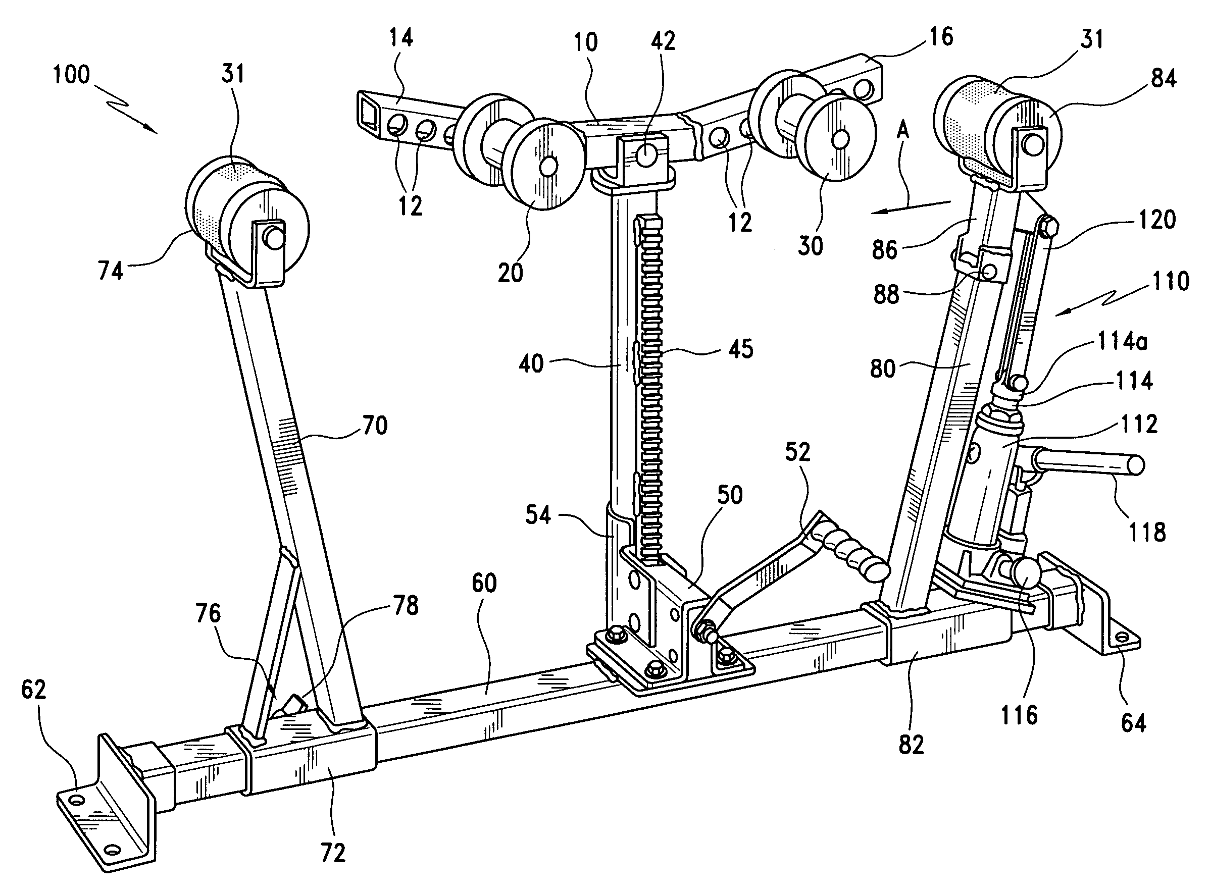
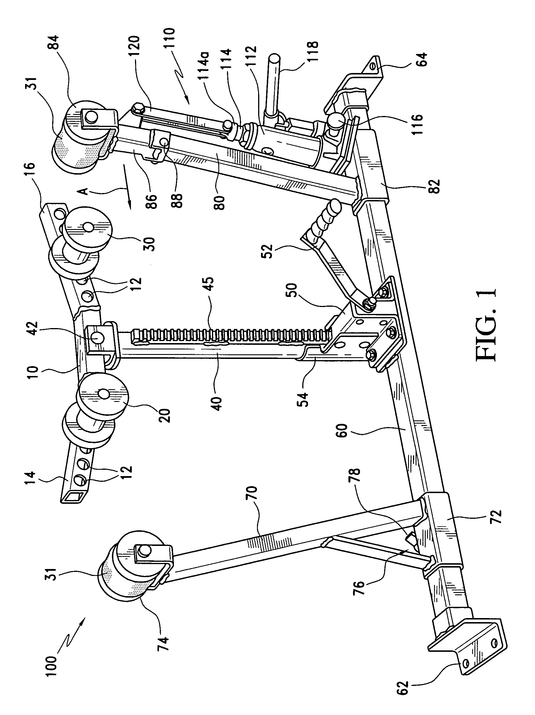
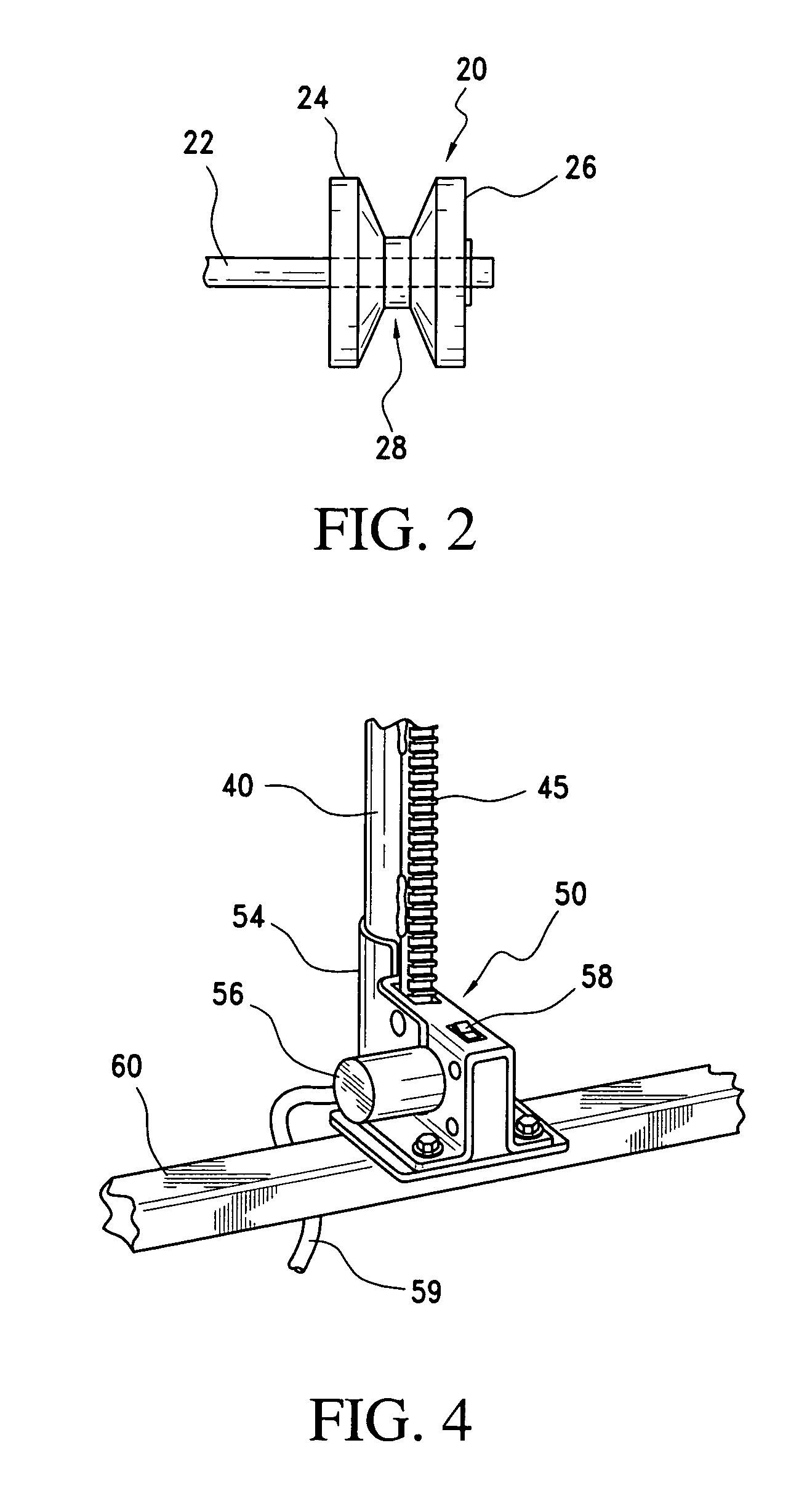
[0023]A bow press 100, according to a first embodiment of the present invention, is shown in FIGS. 1–6. The bow press provides a durable, simple, safe and effective means for maintaining and servicing a variety of types and configurations of bows, particularly parallel limb bows. The bow press 100 includes, in the illustrated embodiment, an inclined riser beam 10 having spaced apertures 12 for receiving and adjustably positioning axles 22 (shown in FIG. 2) of first and second handle rollers 20 and 30. Due to the various shapes of bow handles available today it is important that the handle rollers 20, 30 be adjustably positionable in multiple fixed positions with no possibility of the rollers sliding along riser beam 10 when subjected to the high pressures necessary to compress some bows. Inclined riser beam 10 includes an inclined left end 14 and an inclined right end 16 to define an obtusely-angled V-shape which is important to eliminate interference with various types of attachmen...


PUM


Abstract

A bow press for use in stringing bows includes a base member and left and right inclined spacer bars adjustably positionable along the base member, each spacer bar supporting a bow limb roller thereon. An upper end portion of one spacer bar mounts a bow limb roller, a pivot connector mounts the upper end portion to the spacer bar for pivotal movement of the upper end portion toward and away from the other spacer bar and a hydraulically operated piston or turnbuckle causes the upper end portion to pivot about the pivot connector toward the other spacer bar, whereby a bow limb of the bow is caused to bend toward the other bow limb to release the tension in the bowstring.

Description

CROSS-REFERENCE TO RELATED APPLICATIONS[0001]This application is a continuation-in-part of U.S. application Ser. No. 10 / 884,653, filed Jul. 2, 2004 now U.S. Pat. No. 6,932,070.FIELD OF THE INVENTION[0002]The present invention relates to bow presses and, more particularly, to bow presses for use in stringing or repairing bows, including parallel limb bowsBACKGROUND OF THE INVENTION[0003]Prior to about the 1990s, typical bow designs, whether for hunting or the target range, favored relatively short handles and relatively long limbs. These bows presented little problem for re-stringing or repair since it was a simple matter to apply light downward pressure to the handle, causing the ends of the limbs to move closer to each other for releasing the tension in the bowstring. More recently, bows with longer handles and shorter, more parallel limbs, known as parallel limb bows, have become popular. Due, in part, to the handle designs of many of these bows, and because the limbs approach par...

Claims


Application Information

Patent Timeline
Patent Type & Authority Patents(United States)
IPC IPC(8): F41B5/14
CPCF41B5/14
Inventor KURTZ, JR., GERALD
Owner FLINCHBAUGH COMPANY INC THE
Why Eureka
Try Eureka