Method and system for steering a momentum control system

a technology of momentum control and control system, applied in vehicle position/course/altitude control, process and machine control, instruments, etc., can solve the problem of limited filtering use of active struts

Active Publication Date: 2007-03-06
HONEYWELL INT INC
View PDF10 Cites 21 Cited by
  • Summary
  • Abstract
  • Description
  • Claims
  • Application Information

AI Technical Summary

Problems solved by technology

While distributing the actuators results in a system that generally applies the correct control torques, inefficiencies can result, including duplication of actuator electronics, mechanical structure, and vibration-isolation hardware among these remotely placed units.
In current momentum control systems (MCSs), the use of active struts is limited to filtering disturbances and to responding to the movement of the platform as caused by the movement of the CMGs or RWA.

Method used


Image

  • Method and system for steering a momentum control system
  • Method and system for steering a momentum control system
  • Method and system for steering a momentum control system

Examples


Embodiment Construction

[0015]Active struts, as discussed above, can be used to provide enhanced damping and isolation capabilities over passive struts. This is accomplished by having the active struts react to movements in the MCS such as those caused by changing the speed of a reaction wheel or by the gimbaling of a CMG.

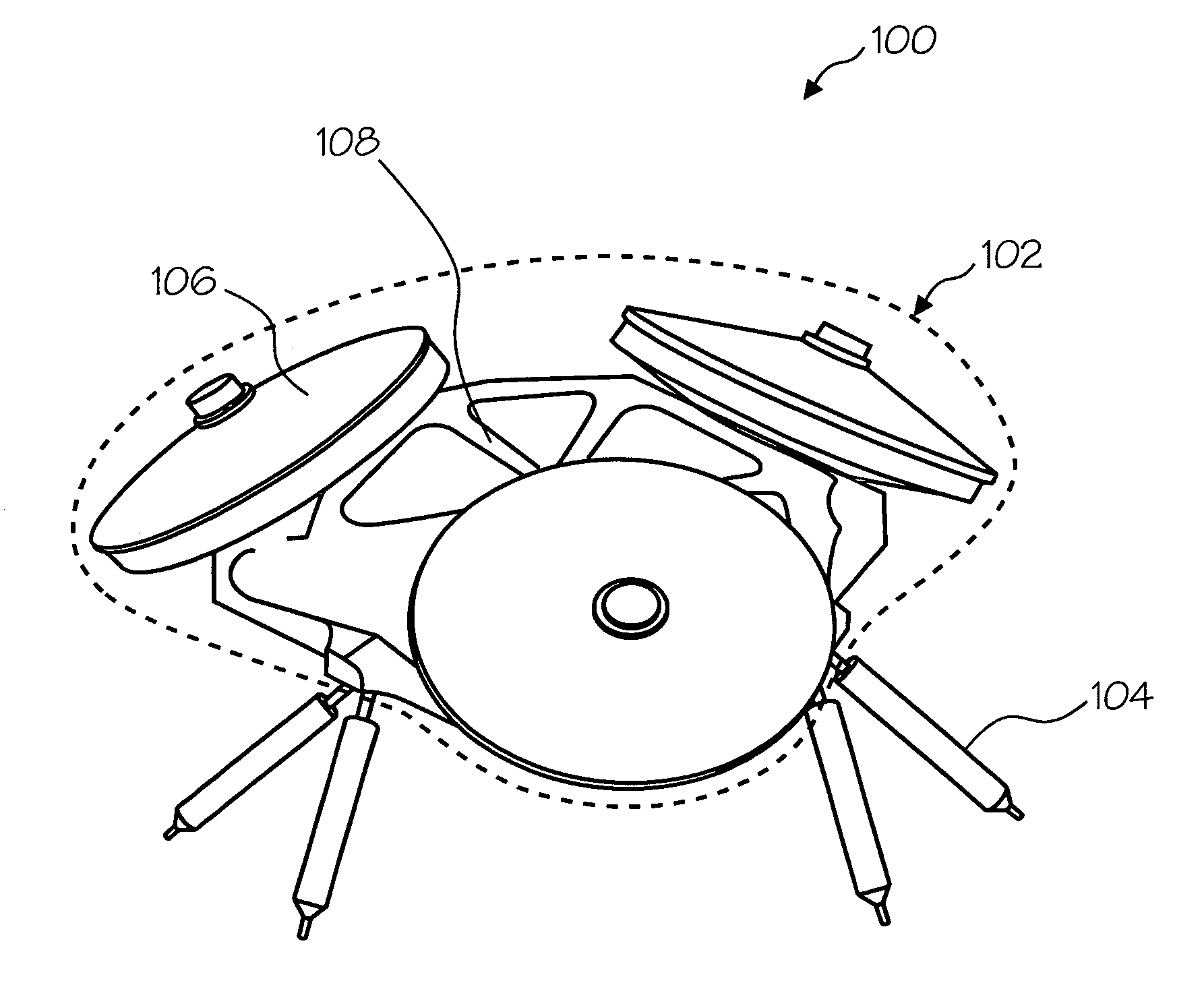
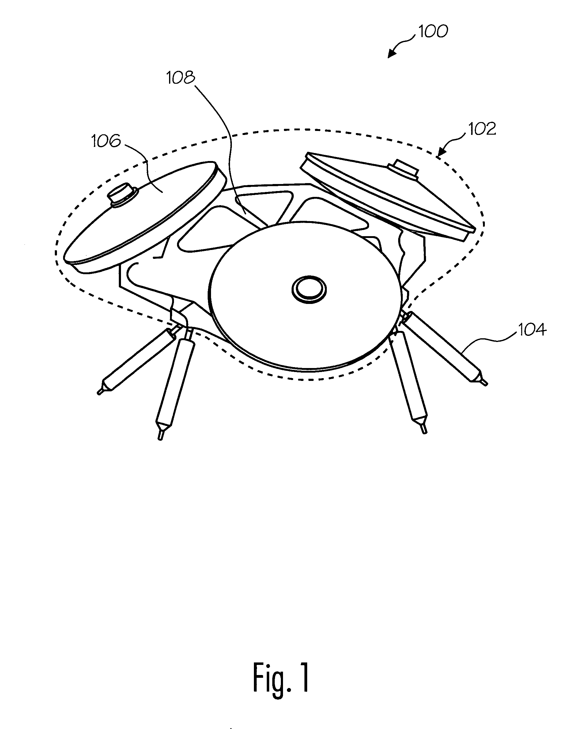
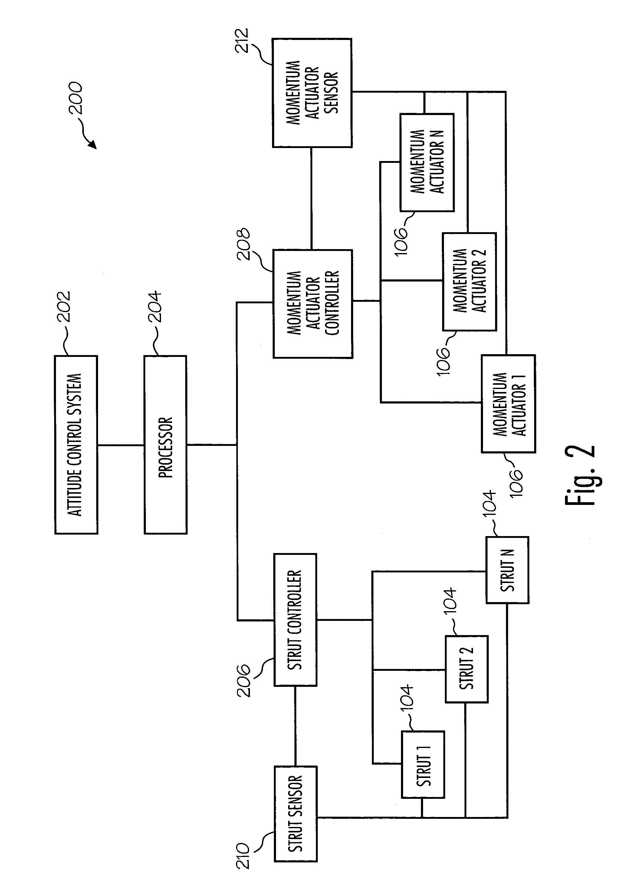
[0016]In the present invention, advantages over previous systems are achieved by using the active struts to manipulate the entire momentum control system's rotational and translational position, rate, and acceleration. For example, FIGS. 1–3 illustrate an embodiment of the present invention. As illustrated in FIG. 1, an exemplary momentum control system (MCS) 100 comprises a momentum-actuator array 102 coupled to a plurality of struts 104. Momentum-actuator array 102 comprises, in the exemplary embodiment of FIG. 1, a plurality of momentum actuators 106 coupled to a platform 108.

[0017]The momentum actuators 106 store momentum and can be manipulated to produce a torque that can be used to ...


PUM


Abstract

A momentum-control system comprising a plurality of momentum actuators and a platform upon which the plurality of momentum actuators are mounted. The momentum control system further comprises a plurality of active struts mounted on the bottom side of the platform. The active struts are configured to produce a force to steer the plurality of momentum actuators and the platform to produce forces and moments for spacecraft attitude control and disturbance suppression.

Description

FIELD OF THE INVENTION[0001]This invention relates to the field of spacecraft vehicle control and, more specifically, to a method and system for steering a momentum control system.BACKGROUND OF THE INVENTION[0002]In order to control the attitude of a spacecraft, various rotating inertia members such as reaction wheel assemblies (RWAs), control momentum gyros (CMGs) and similar actuators are used.[0003]Reaction wheels are typically flywheels that are fixed in the body frame. Torque can be produced by varying the spin rate of the flywheel. The torque produced is produced along the spin axis of the flywheel. A CMG comprises a flywheel with a fixed spin rate mounted to a gimbal assembly. The spin axis of the CMG can be changed by moving the CMG using the gimbal assembly. The torque produced is orthogonal to the spin axis and the gimbal axis. Typically, multiple actuators are oriented such that manipulation of each actuator causes movement about one of at most three linearly independent ...

Claims


Application Information

Patent Timeline
Patent Type & Authority Patents(United States)
IPC IPC(8): B64G1/38B64G1/28G05D1/08
CPCB64G1/285G05D1/0883B64G1/286Y10T74/1221B64G1/244
Inventor PECK, MASON A.
Owner HONEYWELL INT INC
Why Eureka
Try Eureka