Visual indicator for pressurized hub

a technology of visual indicators and hubs, applied in the direction of hubs, instruments, vehicle components, etc., can solve the problems of wheel assembly loss, dangerous scenario of property and possibly life endangerment, bearing and race will typically disintegra

Active Publication Date: 2007-03-06
APPLIED MATERIALS INC
View PDF17 Cites 16 Cited by
  • Summary
  • Abstract
  • Description
  • Claims
  • Application Information

AI Technical Summary

Benefits of technology

[0016]Still another objective of the instant invention is to provide an indicator for law enforcement that hub integrity is intact before allowing trailer placement within a body of water thereby preventing a leaking hub from contamination of water with oil byproducts.
[0017]Yet still another objective of the instant invention is to provide a positive pressure within the hub at all times to prevent the entrance of particles within the hub including water, to prevent premature destruction of the wheel bearing assemblies.
[0018]It is a further objective of the instant invention to provide a hub cap designed to protect wheel bearing assemblies which does not harm natural water environments by facilitating grease expulsion, thereby representing an improvement over the prior art devices.
[0021]The deformable valve portion includes a valve face and a pressure indicating surface moving relative to the outer end of the hub cap in direct relation to the air pressure within the closed air system. The valve face includes tactile indicia to assist an observer to readily identify a breached seal condition within the wheel hub in poor light conditions.

Problems solved by technology

Absence of a lubricant can quickly lead to catastrophic failure of the bearings causing hub disengagement with the axle, which can result in wheel assembly loss and the associated dangerous scenario of property and possibly life endangerment.
For instance, a trailer carrying a heavy load such as a 25 foot boat, will quickly heat up a bearing that is not properly lubricated.
Should the bearing fail, the bearing and race will typically disintegrate with a likely result of the hub and wheel detaching from the axle of the trailer.
Boat trailers present an excellent example of premature wear as a boat trailer is typically submerged in water for loading or unloading of the boat.
Should there be a failure of the hub seal, water is allowed to enter the hub resulting in the premature wear.
In addition, should the water be saltwater, bearing disintegration is greatly enhanced since rust forming on the bearing surfaces will operate to destroy the bearings within very short use.
However, should the hub seal fail, the assembly will actually facilitate grease being pushed through the seal.
Should the spring jam, even if the bearing indicator illustrate that grease is prevalent in the seal, it may be providing a false indication.
Unfortunately, a spring loaded system to pressurize grease into the hub results in an excess amount of grease injected into the hub for proper operation.
This results in an obvious waste of grease for only the bearing rollers must be lubricated.
Of course, the grease continues to leak from the wheel hub because the breach in the seal remains.
The constant expulsion of grease into natural waters by the prior art bearing lubrication systems will have a cumulative negative impact on the environment.
Should the water be a reservoir for drinking water, even a few drops of oil can result in system contamination.
However, it is well known that any oil in water has an adverse effect to wildlife.

Method used


Image

  • Visual indicator for pressurized hub
  • Visual indicator for pressurized hub
  • Visual indicator for pressurized hub

Examples


Embodiment Construction

[0028]Although the invention will be described in terms of a specific embodiment, it will be readily apparent to those skilled in this art that various modifications, rearrangements, and substitutions can be made without departing from the spirit of the invention. The scope of the invention is defined by the claims appended hereto.

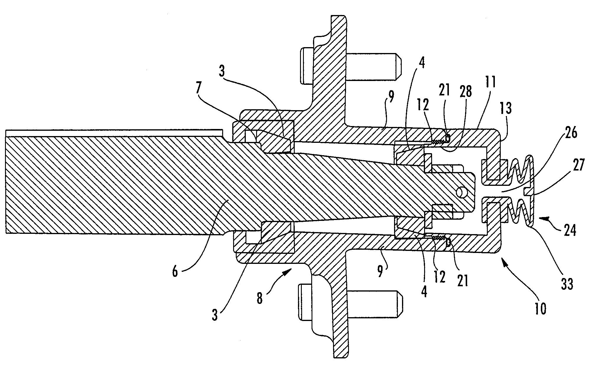
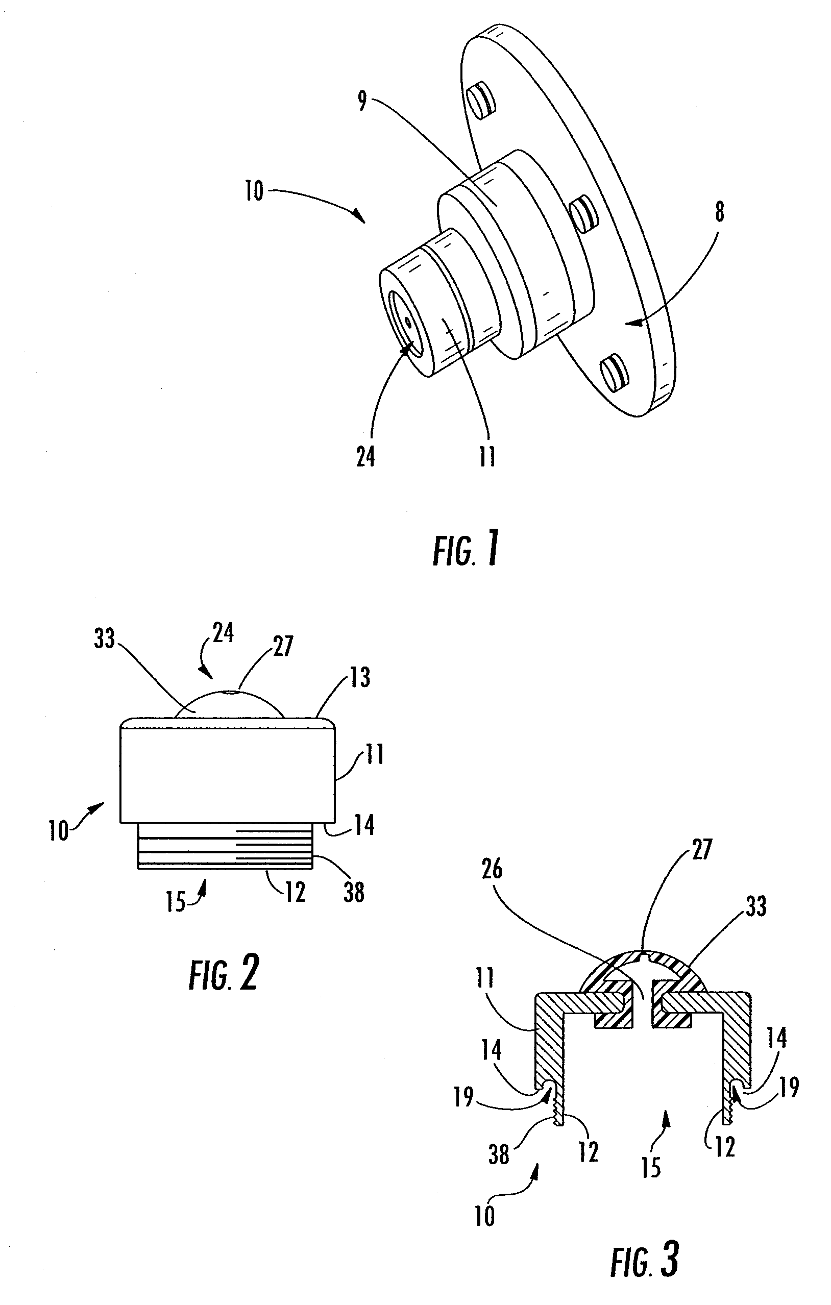
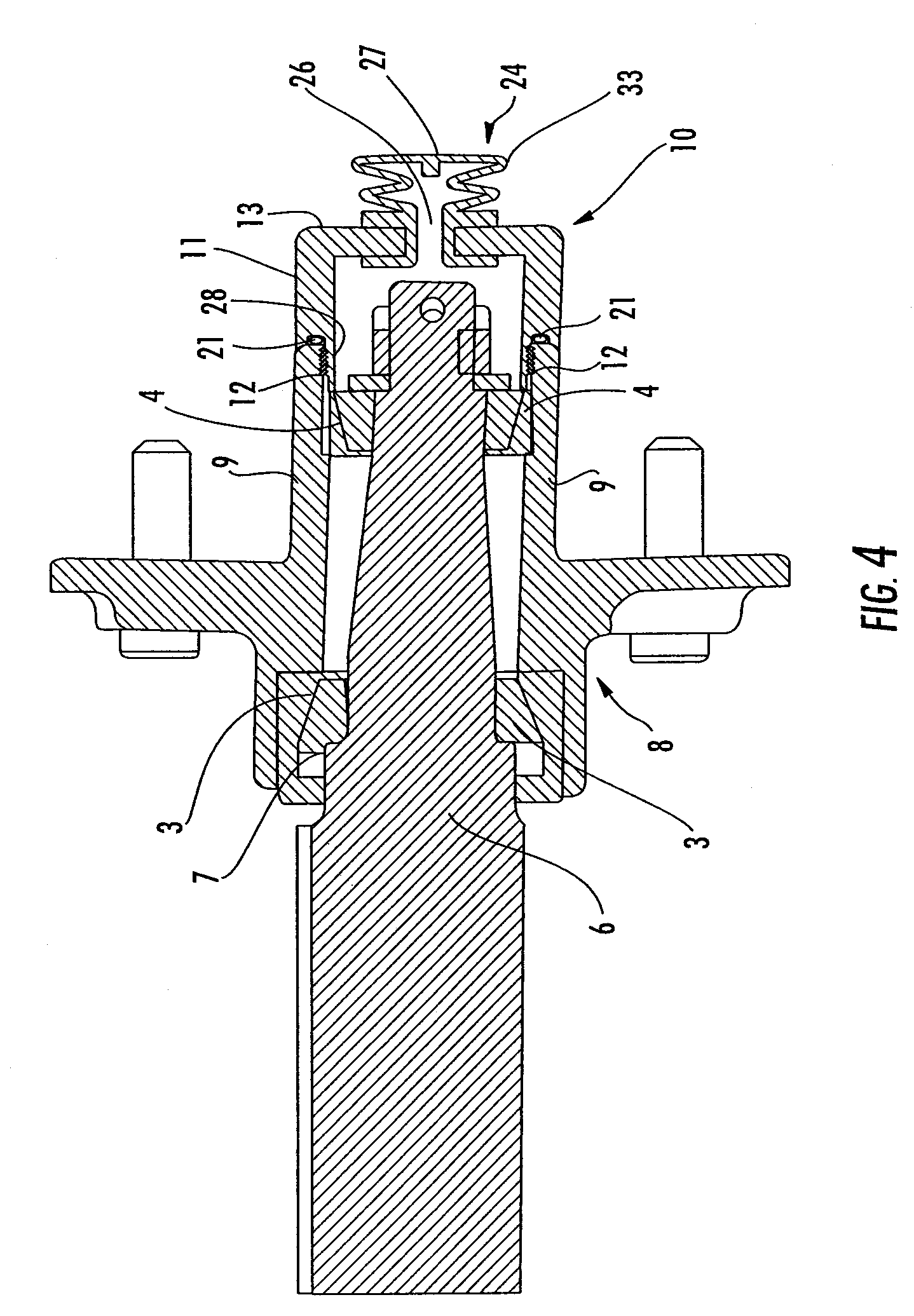
[0029]A hub cap 10 according to a preferred embodiment of the invention is shown in FIGS. 1–3. FIG. 1 illustrates the hub cap 10 as installed to the wheel hub 9 of a boat trailer wheel. FIG. 4 is a cross-sectional view of the hub cap 10 as assembled with a hub 9 of an axle and wheel unit 8 for a trailer. The hub 9 is rotatably supported on bearing assemblies 3 and 4 and mounted on an axle 6. A seal 7 adjacent the inner bearing 3 seals the end of the chamber within the hub 9.

[0030]As best seen in FIGS. 2 and 3, the hub cap 10 of the invention includes a cylindrical housing 11, commonly referred to as a dust cap, having a closed first end 13 and an open seco...


PUM


Abstract

A tactile and visual indicator is mounted on the hub cap of an axle of a vehicle. The indicator has a deformable face that protrudes away from the hub cap in response to the presence of pressurized air in the space containing the wheel bearings. The position of the deformable face indicates the presence or absence of hub integrity and indication of grease about the wheel bearings.

Description

FIELD OF THE INVENTION[0001]This invention is related to the field of wheel hubs and, in particular, to a visual indicator that operates on the pressurization of a wheel hub to indicate hub seal integrity.BACKGROUND OF THE INVENTION[0002]Wheel hubs for use in coupling a tire to an axle are well known. By way of illustration, a conventional trailer for general cargo, boat, snowmobile, personal watercraft, etc. utilizes a fixed axle secured to a trailer frame. A wheel assembly is coupled to the axle by use of a wheel hub. The wheel hub employs a bearing assembly to allow free rotation of the hub in relation to the axle. Thus, the wheel assembly, which includes the tire, permits transportation of the trailer over a road when pulled by a powered vehicle, such as an automobile. The conventional wheel hub employs bearings, namely an inner and outer bearings with an associated inner and outer race, which permits rotational movement in relation to the axle.[0003]As with any friction produci...

Claims


Application Information

Patent Timeline
Patent Type & Authority Patents(United States)
IPC IPC(8): B60B27/00
CPCB60B7/0013B60B7/066B60B27/001B60B27/02B60B27/0073B60B7/14
Inventor DOMBROSKI, HENRY
Owner APPLIED MATERIALS INC
Why Eureka
Try Eureka