Multiform film cooling holes

a film cooling hole and multi-layer technology, applied in the direction of machines/engines, mechanical equipment, liquid fuel engines, etc., can solve the problems of discharged film cooling air jets from the outboard surface, affecting the performance of film cooling holes, and reducing the efficiency of engines

Inactive Publication Date: 2007-03-06
GENERAL ELECTRIC CO
View PDF13 Cites 94 Cited by
  • Summary
  • Abstract
  • Description
  • Claims
  • Application Information

AI Technical Summary

Problems solved by technology

A major objective is to minimize the amount of film cooling air bled from the compressor which is therefore not used in the combustion process and reduces efficiency of the engine.
However, performance of the film cooling holes is affected by the specific geometry thereof and the local conditions in the specific components including the differential pressure or pressure ratio between the outboard and inboard sides of the film cooling holes, and the velocity and pressure distribution of the combustion gases over the outboard surfaces.
The blowing ratio of the differential pressure acting across the component wall affects the tendency of the discharged film cooling air jet to separate or blow-off from the outboard surface which is undesirable.
EDM hole drilling is substantially more expensive than typical laser drilling of the cylindrical film cooling holes, and in view of the large number of film cooling holes typically found in an individual component, substantially increases the cost of manufacturing.
In either configuration, the effective coverage and density of the holes is correspondingly different, and correspondingly affects film cooling air performance, as well as the cost of manufacture due to the different complexity thereof.

Method used


Image

  • Multiform film cooling holes
  • Multiform film cooling holes
  • Multiform film cooling holes

Examples


Embodiment Construction

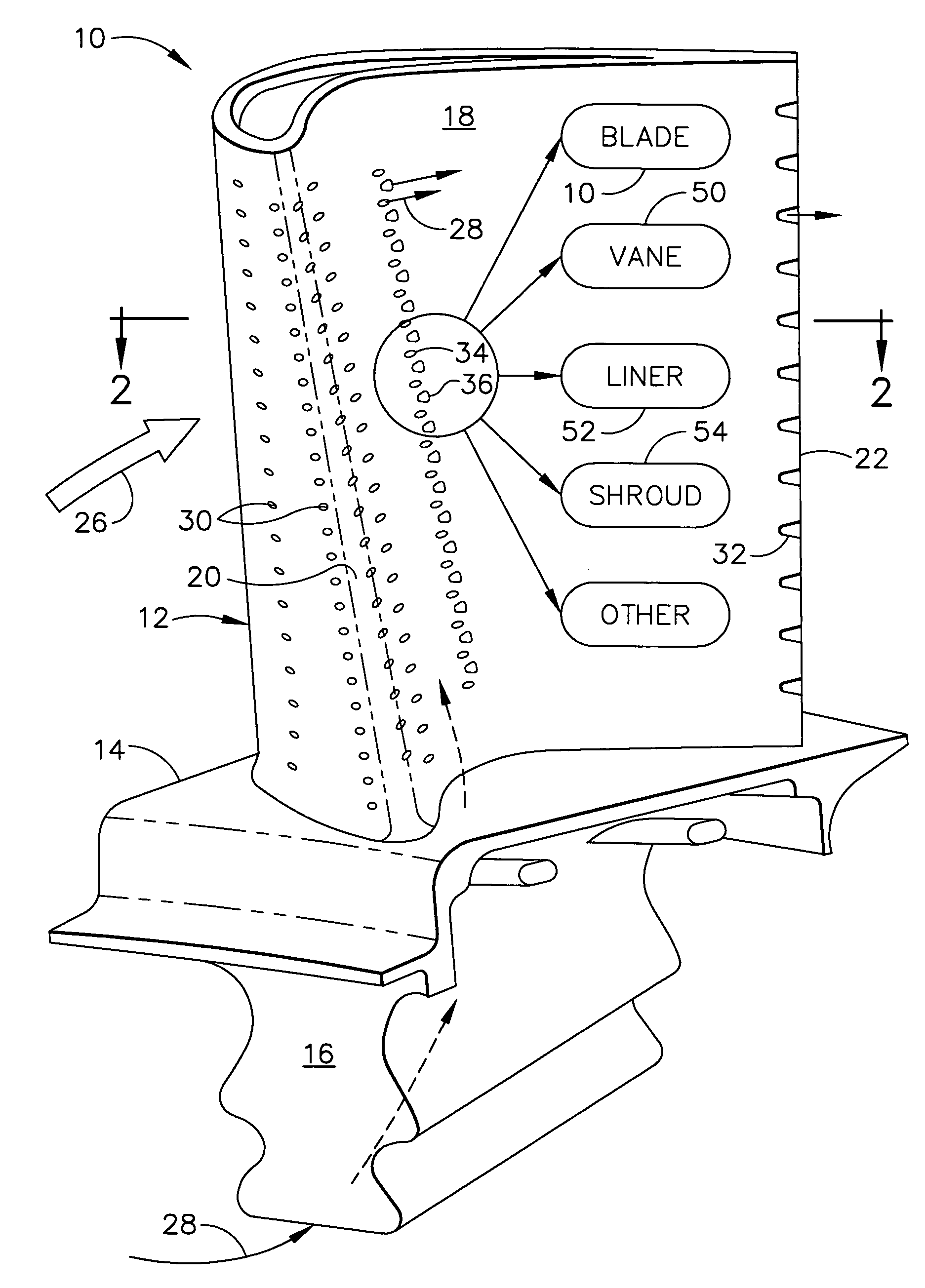
[0032]An exemplary component of a gas turbine engine in the form of a turbine rotor blade 10 is illustrated in FIG. 1. The blade includes an airfoil 12 integrally joined to a platform 14 at the root thereof which in turn is joined to a supporting axial-entry dovetail 16 for mounting the blade to the perimeter of turbine rotor disk (not shown) is a conventional manner.

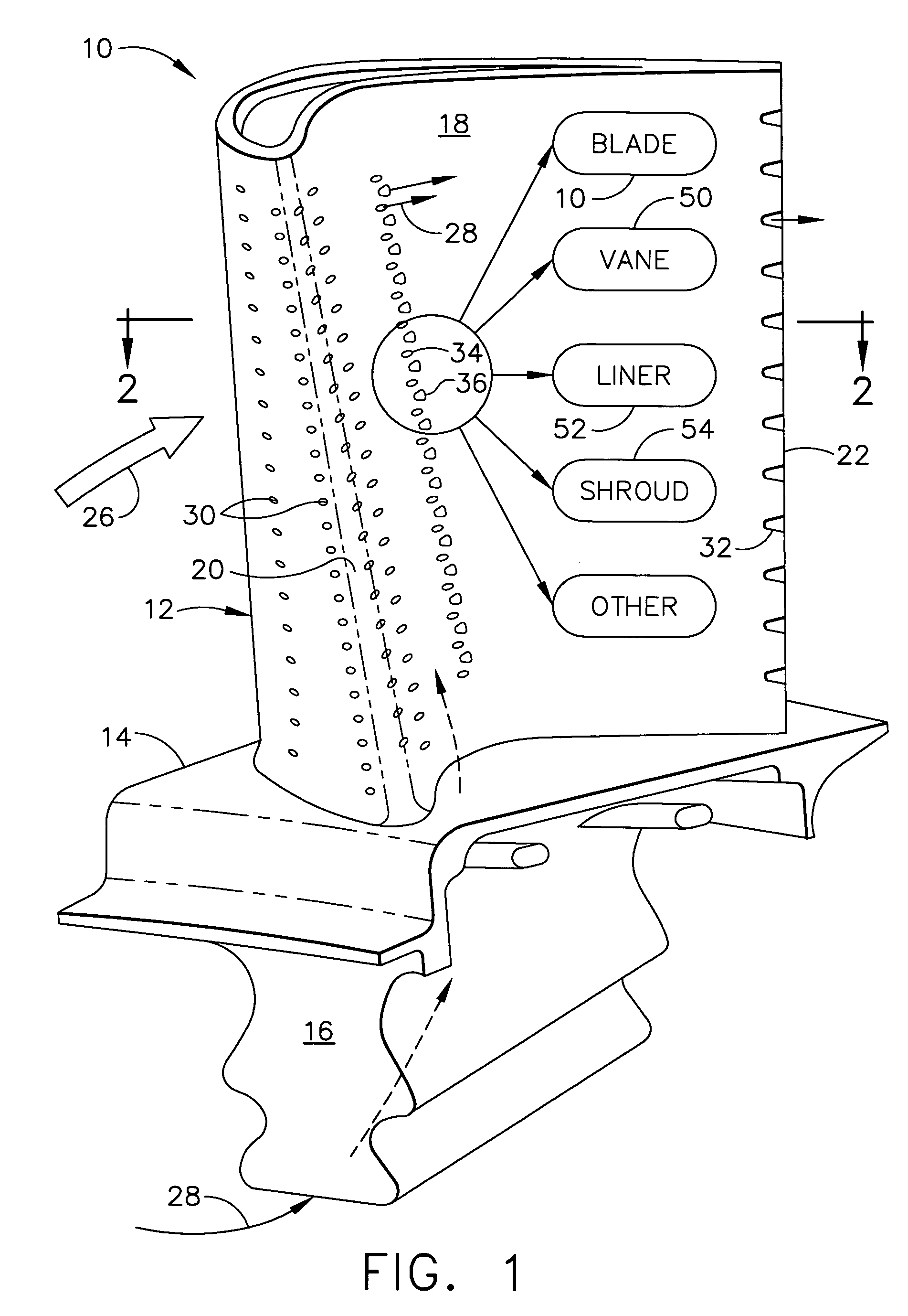
[0033]As additionally shown in FIG. 2, the airfoil is hollow and is bounded by a thin sidewall 18 which defines a generally concave pressure side of the airfoil and an opposite, generally convex suction side of the airfoil which extend in chord in the axial downstream direction between a leading edge 20 and an opposite trailing edge 22.

[0034]The airfoil includes an internal cooling circuit 24 which may have any conventional configuration and typically includes radially extending channels separated by radial partitions bridging the two sides of the airfoil in one or more dedicated circuits, typically including multi-pass...


PUM


Abstract

A turbine wall includes a plurality of first and second film cooling holes arranged in a common row. The holes have multiple forms and alternate in the row for collectively providing film cooling performance therefrom.

Description

BACKGROUND OF THE INVENTION[0001]The present invention relates generally to gas turbine engines, and, more specifically, to cooling therein.[0002]A typical gas turbine engine includes a multistage compressor that pressurizes air which is then mixed with fuel in a combustor for generating hot combustion gases. Energy is extracted from the gases in multiple turbine stages for powering the compressor and producing useful work by powering a fan in an aircraft turbofan application, or powering an output shaft for marine and industrial applications.[0003]The hot combustion gases flow along various components of the engine, which in turn are typically cooled by using a portion of the pressurized air bled from the compressor. For example, the combustion gases are born in the combustor which is typically defined by radially outer and inner annular combustion liners. The liners are typically provided with film cooling holes extending therethrough through which the pressurized compressor bleed...

Claims


Application Information

Patent Timeline
Patent Type & Authority Patents(United States)
IPC IPC(8): F01D5/08F01D5/18
CPCF01D5/186F01D5/20F05D2260/202Y02T50/676Y02T50/60
Inventor LEE, CHING-PANG
Owner GENERAL ELECTRIC CO
Why Eureka
Try Eureka