Foot-operated controller

a foot-operated controller and foot-operated technology, applied in the field of foot-operated controllers, can solve the problems of conventional foot-operated controllers not being practical for simultaneously controlling multiple functions in a more complicated device, conventional prostheses not meeting many basic needs of individuals, and limitations of foot-operated controllers

Inactive Publication Date: 2007-03-06
JEFFREY ELKINS 2002 TRUST
View PDF52 Cites 49 Cited by
  • Summary
  • Abstract
  • Description
  • Claims
  • Application Information

AI Technical Summary

Benefits of technology

[0016]In a less refined aspect, the microprocessor may be hard-wired to the controllable electromechanical device, eliminating the need for a radio transmitter. In such case, the microprocessor may be located either in the shoe (e.g., on the substrate), or in / on the controllable electromechanical device.

Problems solved by technology

Foot-operated controllers have traditionally been limited to pedals mechanically linked to valves, levers, regulators or the like, such as accelerator and brake pedals for automobiles, or pedals capable of generating only a single electrical signal, such as for controlling a sewing machine.
These conventional foot-operated controllers are not practical for simultaneously controlling multiple functions in a more complicated device such as a prosthetic hand.
The conventional prostheses do not satisfy many of the basic needs of individuals who have either lost a limb or were born without a limb.
However, this device can only be used by individuals having a forearm and some phantom feeling (i.e., the sense that they can still feel their missing hand).
However, there is not any independent finger or wrist control.

Method used


Image

  • Foot-operated controller
  • Foot-operated controller
  • Foot-operated controller

Examples


Embodiment Construction

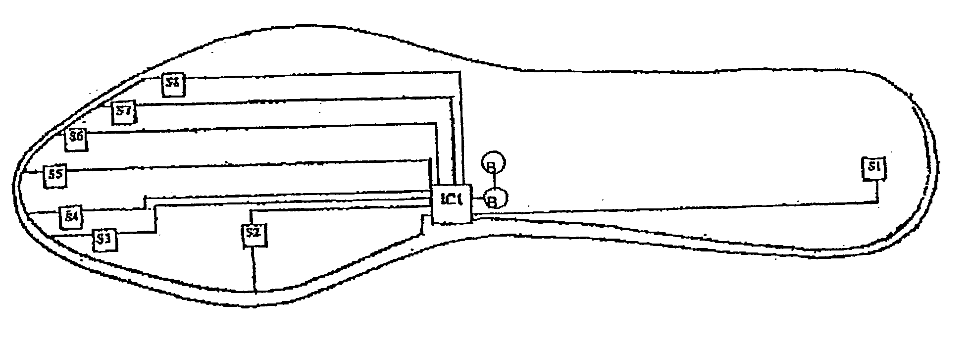
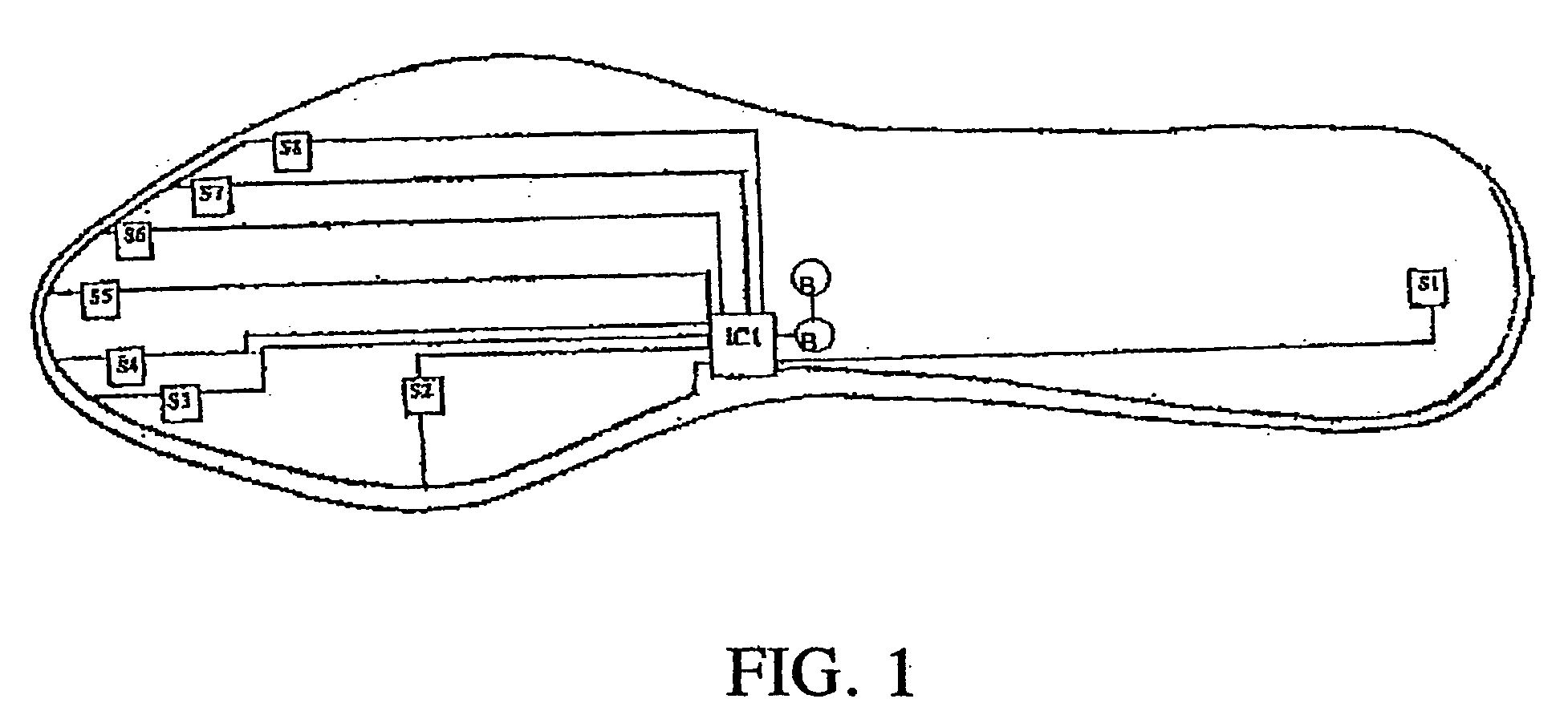
[0025]There are located in a shoe insole insert, eight pressure sensors. FIG. 1, depicts the layout of the shoe insole insert.

[0026]The shoe insole insert constitutes a foot-operated controller that includes two miniature lithium batteries (B); an integrated circuit (IC) board, which includes a microcontroller and a microradio transmitter; and, eight pressure sensors (S1 through S8). The correspondence of the sensor locations to the movements of the wrist and hand, in the hand prosthesis application, are as follows:

[0027]

LocationFootHandS1HeelWrist flexion / extensionS2BallWrist pronation / supinationS3Inside of great toeThumb inversion / eversionS4Great toeThumb flexion / extensionS5Second toeSecond finger flexion / extensionS6Third toeThird finger flexion / extensionS7Fourth toeFourth finger flexion / extensionS8Fifth toeFifth finger flexion / extension

[0028]The number, eight, is significant in that miniature electronic elements are packaged in powers of two; namely 2, 4, 8, 16, etc . . . . Eight...


PUM


Abstract

A practical control device having up to eight independent channels of communication for simultaneously operating a plurality of electromechanical devices or for simultaneously performing a plurality of independent functions on an electromechanical device, such as a prosthetic hand, includes a foot-operated controller and a microprocessor. The foot-controller includes a plurality of pressure sensors mounted at selected locations on a substrate. The microprocessor converts sensor inputs from the foot-operated controller into commands for a controllable electromechanical device such as a prosthetic hand. Commands may be communicated via a radio transmitter or via hard-wiring.

Description

CROSS-REFERENCE TO RELATED APPLICATION[0001]This application claims priority under 35 U.S.C. § 119(e) on U.S. Provisional Application No. 60 / 418,508 entitled FOOT-OPERATED CONTROLLER, filed Oct. 15, 2002, by Jeffrey L. Elkins, the entire disclosure of which is incorporated herein by reference.FIELD OF THE INVENTION[0002]This invention relates to foot-operated controllers, and more particularly to foot-operated controllers for generating a plurality of independent signals.BACKGROUND OF THE INVENTION[0003]Foot-operated controllers have traditionally been limited to pedals mechanically linked to valves, levers, regulators or the like, such as accelerator and brake pedals for automobiles, or pedals capable of generating only a single electrical signal, such as for controlling a sewing machine. These conventional foot-operated controllers are not practical for simultaneously controlling multiple functions in a more complicated device such as a prosthetic hand.[0004]Annually, approximatel...

Claims


Application Information

Patent Timeline
Patent Type & Authority Patents(United States)
IPC IPC(8): A61F2/48A61F2/70H01H3/14A61F2/76
CPCA61F2/68A61F2/70G05B2219/45172A61F2002/705A61F2002/7635A61F2002/704
Inventor ELKINS, JEFFREY L.
Owner JEFFREY ELKINS 2002 TRUST
Why Eureka
Try Eureka