System and a method of three-dimensional modeling and restitution of an object

a three-dimensional modeling and object technology, applied in surveying and navigation, instruments, navigation instruments, etc., can solve the problems of varying distances, problems such as the inability to accurately reflect reality, and the inability to accurately represent the object to be modelled

Active Publication Date: 2007-03-06
YODEA +1
View PDF6 Cites 32 Cited by
  • Summary
  • Abstract
  • Description
  • Claims
  • Application Information

AI Technical Summary

Benefits of technology

[0041]The aim of the invention is to provide a system for three-dimensional modeling and restitution of an object, which system is lightweight and self-contained, and in particular implements the above-described photogrammetric technique.
[0051]Overall, the system is in the form of a system that is lightweight and self-contained, transportable by an operator who can thus move in a measurement field that is a priori of large dimensions.
[0053]It is explained in detail below how the measurements obtained can be very accurate and how the apparatus does not need to be handled by an expert, since it is simple to operate.
[0056]In a more preferred variant embodiment of the invention, additional members may be combined with the basic members of the first subsystem, e.g. for the purpose of obtaining additional measurement accuracy and / or for making the first subsystem easier to handle.

Problems solved by technology

This ideal representation is nevertheless not an accurate reflection of reality.
Unfortunately, the size of the projection center depends on the size of the aperture while the picture is being taken.
Unfortunately, this distance varies during focusing.
Similarly, if there is a change in the focal length, c is modified;outlining: one of the traditional difficulties in the technique of photogrammetry is the problem of outlining the objects to be modelled.
The photogrammetric technique gives rise to errors of parallax if measurements (of position, etc.) are not taken with sufficient accuracy.
With systems of that type it is indeed possible to achieve good accuracy, however they generally present rather numerous drawbacks that can be summarized as follows: the equipment is heavy and difficult to transport, its range of action is small, its cost is high, the system can only be used by specialists since it is complex to operate, and image processing is laborious and subject to error.
Nevertheless, that does not mean they are free from drawbacks, and in particular they suffer from the following: they are difficult and lengthy to implement since it is necessary to install expensive targets, the field of measurement is limited to the area where the targets have been installed, and once again that type of system is suitable for use only by specialists since it is complex to operate.
That technique is limited in practice to objects of small dimensions only.
Because of the characteristics inherent to the method, the colors of the object are spoilt by the processing.
The processing is complex, and as a result that type of system is for use by specialists only.
It is then necessary to identify manually on each photograph a maximum number of remarkable points that are common to all of the photographs, and, a priori, that operation is time consuming.
However it is not free from drawbacks, and in particular it requires manual preprocessing that is laborious, as mentioned above, and the resulting accuracy is poor, as is inherent to any manual processing.
Its disadvantages are likewise similar: lengthy image preprocessing, manual intervention required to eliminate errors, and poor accuracy.
Nevertheless like the preceding system it can only be applied to objects of small size.
In addition, it turns out to be lengthy and expensive to implement.
Systems and methods exist which enable good accuracy to be achieved concerning the positions of the photographs, but in the present state of the art, those methods are expensive, requiring complex infrastructure, and therefore difficult to implement (and indeed relying on specialists) and there are constraints on the size of the object that is to be modelled.
Implementation is simple, but the accuracy of the resulting data generally turns out to be too coarse, and manual intervention is also generally needed.
As a result, processing is slow and subject to error.
As a general rule, the resulting difficulties are such that, in practice, use is made of systems based on laser telemetry.
Such systems have the advantage of measuring the dimensions of elements constituting objects, but they also have the unavoidable drawback of being too coarse compared with traditional images and of being incapable of processing color information, specifically because laser sources are used.

Method used


Image

  • System and a method of three-dimensional modeling and restitution of an object
  • System and a method of three-dimensional modeling and restitution of an object
  • System and a method of three-dimensional modeling and restitution of an object

Examples


Embodiment Construction

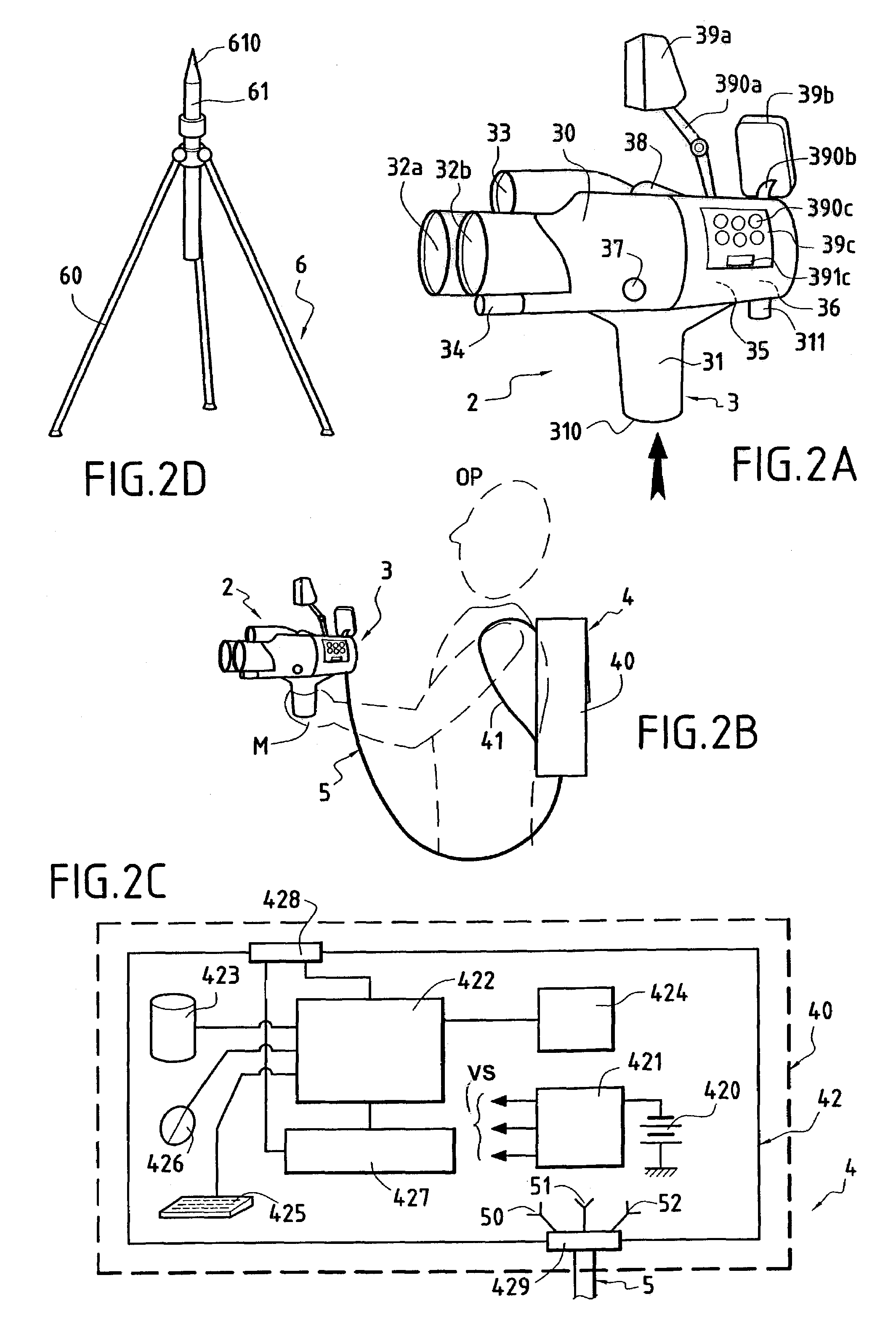
[0068]There follows a description of the system for three-dimensionally modeling and restitution an object constituting a preferred embodiment of the invention, given with reference to FIGS. 2A to 2D.

[0069]To simplify the description, terms such as “three-dimensional” or “in three dimensions” are replaced below by the abbreviation “3D”.

[0070]In the figures, elements that are identical have the same references and are described again only where necessary.

[0071]FIG. 2A is a diagram of that which is referred to below as the “first” subsystem 2 in a system of the invention.

[0072]This subsystem 2 is essentially constituted by a housing 3 similar in appearance to a video camera, a camcorder, or the like. The housing 3 comprises a rigid cell 30 advantageously made of magnesium alloy, thus ensuring that it is both rigid and lightweight. In conventional manner, the shell is provided with a bottom handle 31.

[0073]The first subsystem 2 comprises firstly, in the housing 3, optical elements.

[007...


PUM


Abstract

A system for three-dimensionally modeling and restitution a subject, the system comprising a housing suitable for being carried in the hand by an operator, the housing having an optical unit with stereoscopic digital video cameras co-operating with an inertial navigation unit having a trihedron of optical fiber gyros and a trihedron of accelerometers for generating position and displacement signals in a frame of reference. The housing may also include, in particular, a telemeter laser, an infrared video camera, a GPS unit, inclinometers, and tri-flux magnetometers. A second subassembly connected to the housing by an optical and / or electrical connection cable contains an electrical power supply, electronic circuits, and a microcomputer for processing signals delivered by the housing and for generating a three-dimensional model of the subject, implementing a photogrammetric technique.

Description

[0001]The invention relates to a system for three-dimensional modeling and restitution of an object.[0002]The invention also relates to a method of modeling an object in three dimensions by implementing the system of the invention.[0003]More particularly, the invention applies to a system that is lightweight and self-contained, implementing in particular a so-called “photogrammetric” technique.BACKGROUND OF THE INVENTION[0004]Before outlining the characteristics of prior art systems and methods and describing the systems and methods that are specific to the invention in greater detail, it is appropriate to begin by briefly summarizing the main characteristics of the above-mentioned photogrammetric technique, with reference to FIG. 1 accompanying the present description.[0005]Photogrammetry is a technique for determining the shape, the dimensions, and the position of an object, on the basis of perspective views of said object recorded using photographic methods.[0006]In the context o...

Claims


Application Information

Patent Timeline
Patent Type & Authority Patents(United States)
IPC IPC(8): H04N15/00G01C11/06G01C21/16H04N13/239
CPCG01C11/06G01C21/16H04N13/0253H04N13/0239H04N2013/0081H04N13/254H04N13/239G01C21/188
Inventor ALHADEF, BERNARDALHADEF, LAURENT
Owner YODEA
Why Eureka
Try Eureka