Versatile antenna switch architecture

a switch architecture and antenna switch technology, applied in the direction of substation equipment, electrical equipment, discontnuous tuning with seperate pretuned circuits, etc., can solve the problems of increasing the complexity of the rf front-end, not being able to combine a 1900 duplexer and a 2100 duplexer for eu/us wcdma operations, and not being able to use a diplexer approach. , to achieve the effect of combining

Active Publication Date: 2007-03-06
NOKIA TECH OY
View PDF12 Cites 84 Cited by
  • Summary
  • Abstract
  • Description
  • Claims
  • Application Information

AI Technical Summary

Problems solved by technology

If more than one WCDMA or CDMA band is required in addition to the quad-band GSM bands, the complexity of the RF front-end increases significantly.
For example, it is not feasible to use a diplexer approach to combine a 1900 duplexer and a 2100 duplexer for EU / US WCDMA operations.
Furthermore, if the bands overlap in frequency (e.g. 1800 and 1900 bands), the diplexer approach is equally impossible.
Due to the large number of different bands and the number of combinations thereof in different systems used around the world, using traditional methods and topologies for band selection and mode switching is difficult.
It would be difficult to implement all these different variants efficiently if the GSM and WCDMA modes are handled separately and no switching is used for WCDMA.

Method used


Image

  • Versatile antenna switch architecture
  • Versatile antenna switch architecture
  • Versatile antenna switch architecture

Examples


Embodiment Construction

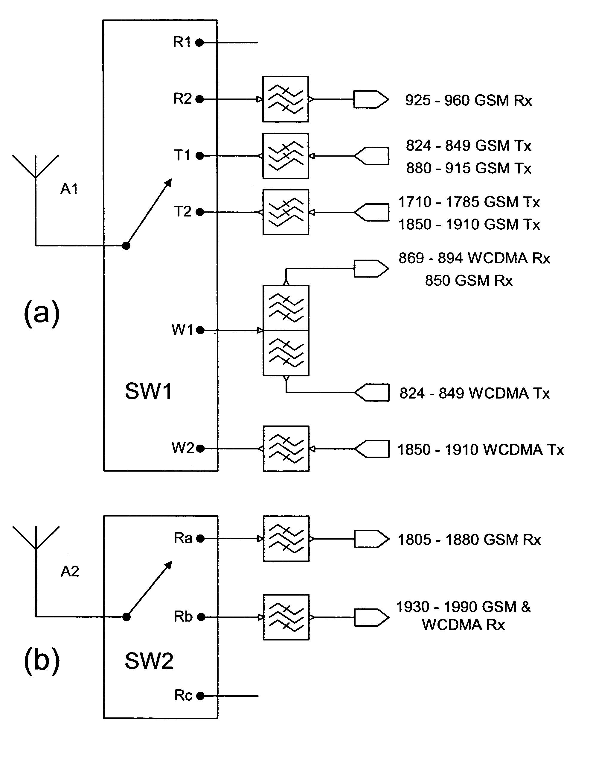
[0087]The present invention uses two antenna switches to route various transmit and receive paths to two separate antennas. In particular, one of the antenna switches is used to route the 2 GHz receive paths, and another antenna switch is used for switching among the 2 GHz transmit paths and the 1 GHz signal paths. As shown in FIGS. 3 to 7, SW2 is the antenna switch module for 2 GHz receive paths and comprises three switch positions (SP3T) separately labeled as Ra, Rb and Rc. As such, up to three receive paths can be connected to SW2. The other antenna switch module, or SW1, comprises six switch positions (SP6T) separately labeled as R1, R2, T1, T2, W1, W2. As such, up to six signal paths can be connected to SW1. In the illustrative examples in FIGS. 3 to 7, the switch positions W1 and W2 are two full-duplex branches for routing WCDMA / CDMA signal paths; the switch positions R1 and R2 are used for routing 1 GHz receive paths; the switch position T1 is used for routing the 1 GHz trans...


PUM


Abstract

A RF front-end having two antenna switches operatively connected to two separate antennas. The antenna switches can be used to route various transmit and receive paths to the antennas. In particular, one of the antenna switches has three switch position for use in selectively routing the 2 GHz receive paths, and another antenna switch has six switch positions for use in selectively routing the 2 GHz transmit paths and the 1 GHz signal paths. With the disclosed topology, the front-end can be used to support GSM and W-CDMA communications in many regional variants in the world. The supported variants include US1, US2, EU1, EU2 and EU / US modes. The same front-end can also be used in BT / WLAN connectivity. For MIMO purposes, one more antenna switch for the 2 GHz receive paths can be added to the same RF front-end.

Description

CROSS REFERENCE TO RELATED APPLICATIONS[0001]The present application is related to U.S. patent application Ser. Nos. 10 / 688,181, 10 / 688,275 and 10 / 688,807, all filed on Oct. 17, 2003, and assigned to the assignee of the present application. The present application is also related to U.S. patent application Ser. No. 10 / 836,123, assigned to the assignee of the present application, and filed even date herewith.FIELD OF THE INVENTION[0002]The present invention generally relates to an RF front-end module and, more specifically, to an RF front-end for use in GSM and WCDMA communications.BACKGROUND OF THE INVENTION[0003]In an electronic device for use in GSM and WCDMA communications, the multimode engine has a duplexer to feed WCDMA transmit and receive paths to a WCDMA antenna, and a dedicated GSM antenna / switch module is used for the GSM modes, as shown in FIG. 1. In this dual antenna topology, no antenna switching is required between GSM and WCDMA modes. As shown, the GSM antenna switch...

Claims


Application Information

Patent Timeline
Patent Type & Authority Patents(United States)
IPC IPC(8): H04M1/00H03J5/24H04B1/44H04B1/48
CPCH04B1/48H03J5/244
Inventor RANTA, TEROELLA, JUHA
Owner NOKIA TECH OY
Why Eureka
Try Eureka