
Fastener device

a technology of fasteners and components, applied in the direction of threaded fasteners, snap fasteners, screw fasteners, etc., can solve the problems of difficult inserting of fingers or long-nose pliers, components cannot be used to attach other components, and the effect of easy attachmen

Inactive Publication Date: 2007-03-13
NEWFREY
View PDF8 Cites 41 Cited by
  • Summary
  • Abstract
  • Description
  • Claims
  • Application Information

AI Technical Summary

Benefits of technology

The present invention provides an improved fastener device that allows for easy attachment and detachment of components. The fastener device includes a clip with a flange and a hollow shank, and elastic engagement leaves formed on the sides of the shank. A retaining plate engages the elastic engagement leaves and works with the flange to hold a first component between them. The shank is inserted into a second component, and the elastic engagement leaves engage an edge of the through-hole in the second component. The retaining plate can be easily detached from the clip by applying an external force to move the retaining plate away from the clip. The fastener device allows for easy attachment and detachment of components, even in a dark place. The engagement leaves are designed to move inward with respect to the shank when the retaining plate and the clip are arranged within a predetermined interval. The retaining plate also has third engagement leaves to engage the second component at a side opposite to the first elastic engagement leaves. A bore is formed in both the flange and the shank of the clip, and a pin is provided for insertion into the bore to keep the first engagement leaves from bending inward with respect to the shank.

Problems solved by technology

However, the release arms protrude on the upper surface of the flange in a difficult mounting position.
Also, the upper surface of the flange is not flat and, thus, cannot be used to attach other components.
However, the cord has to operate within a narrow space and components cannot be detached if the cord becomes severed or is lost.
However, a finger or a tool such as longnose pliers has to be used to apply, pressure to the release arm.
It is difficult to insert a finger or longnose pliers due to the panel-shape of the second component, and the release operation is difficult to perform in a dark place where visibility is low.

Method used


Image

  • Fastener device
  • Fastener device
  • Fastener device

Examples


Embodiment Construction

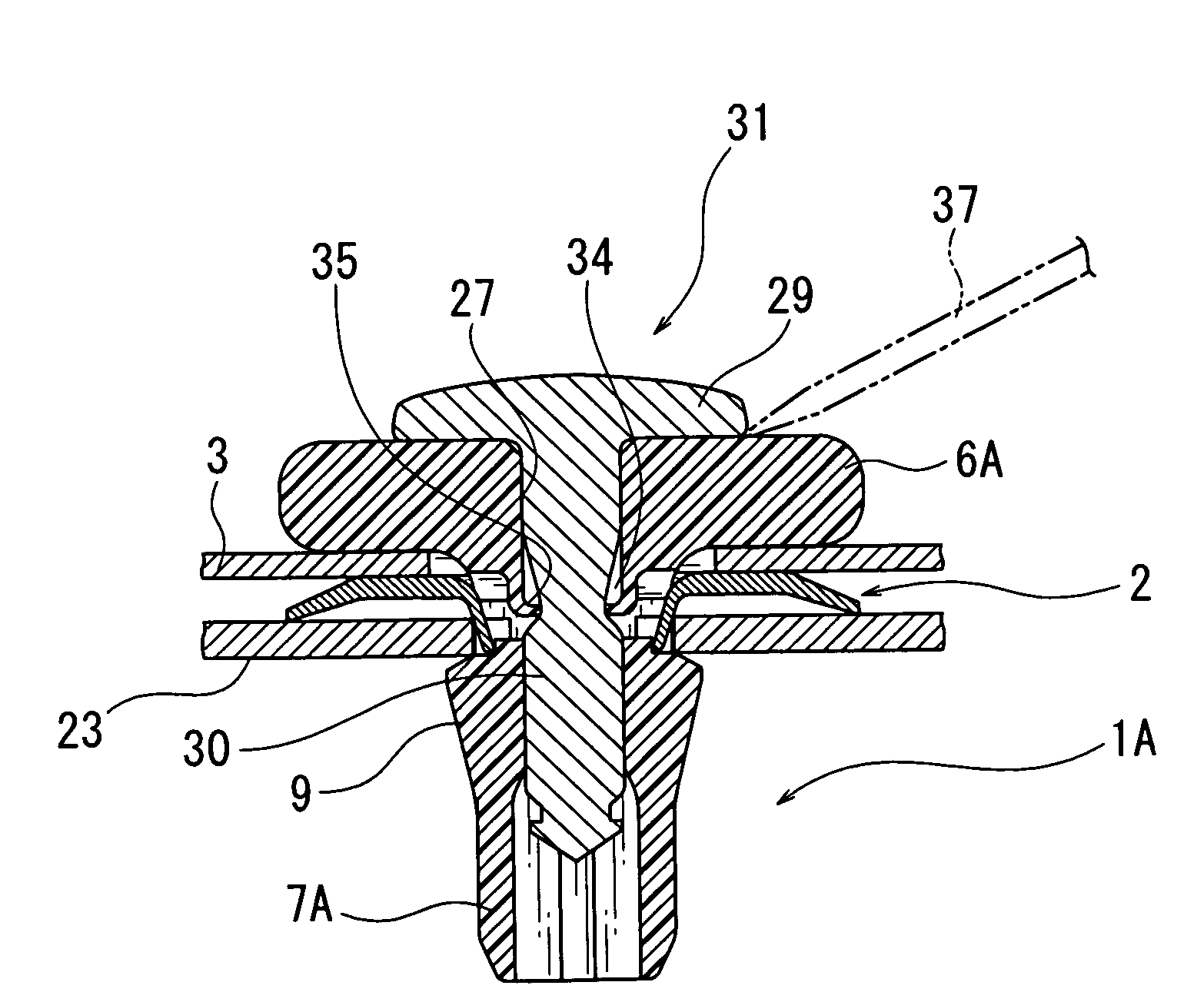
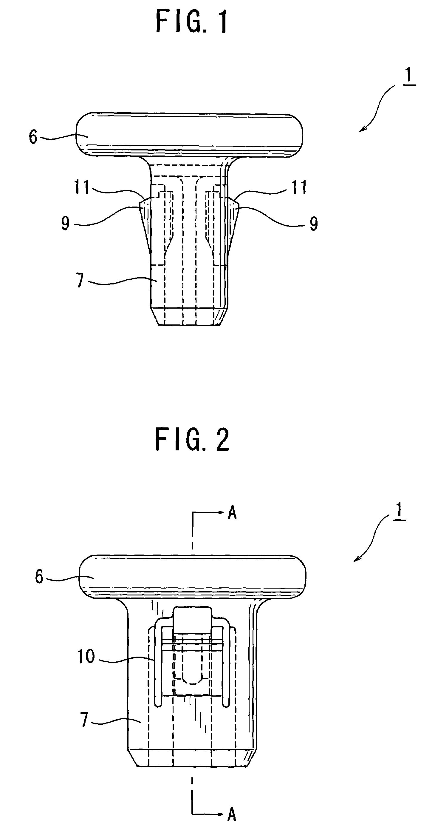
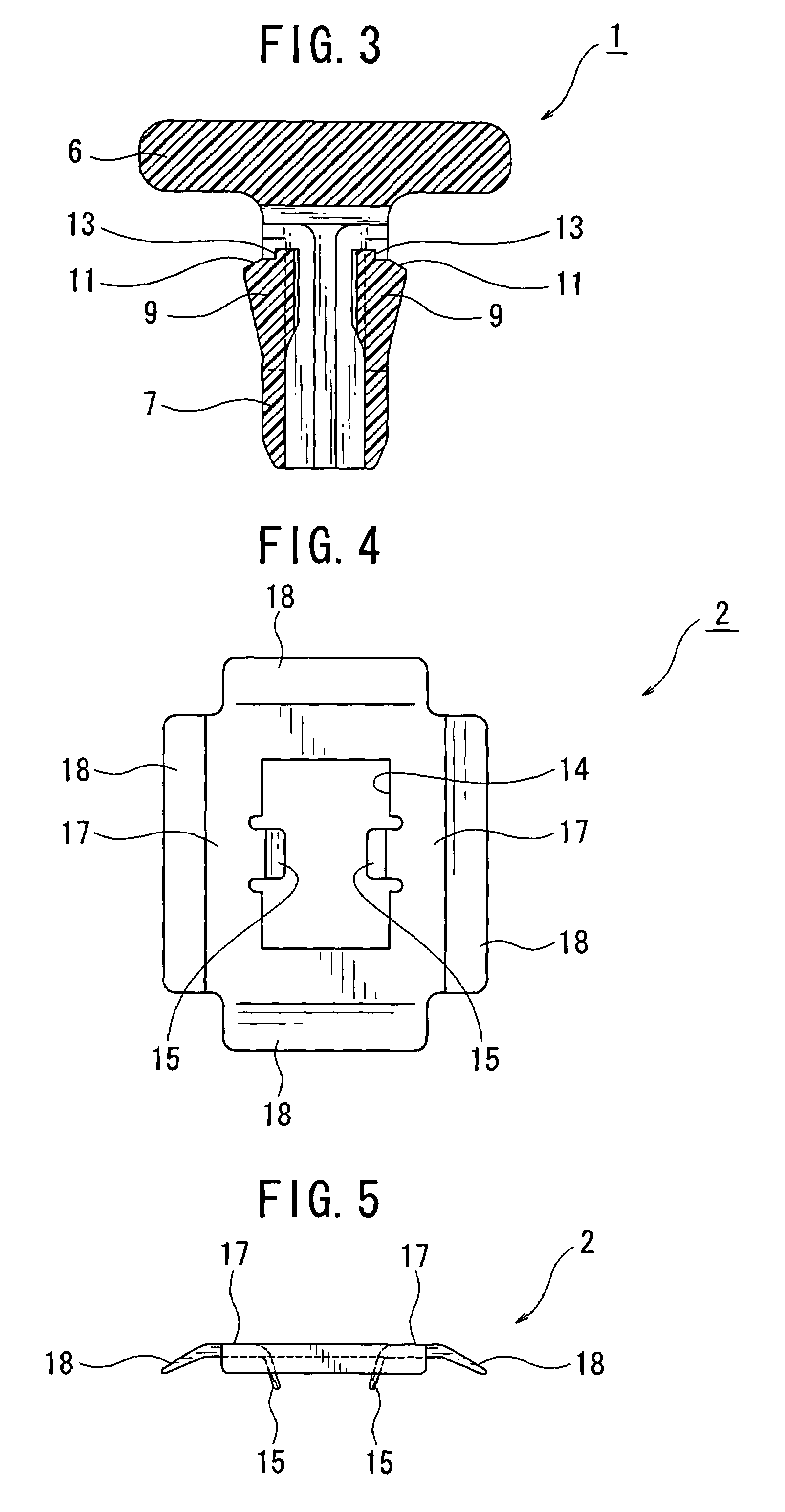
[0030]The following is a detailed explanation of examples of the present invention with reference to the drawings. The fastener device 5 comprises the clip 1 in FIG. 1 through FIG. 3 and the retaining plate 2 in FIG. 4 and FIG. 5. As shown in FIG. 6, the clip 1 and the retaining plate 2 are about to engage a first component 3 from opposite sides to hold it in place. In FIG. 7, the fastener device 5 comprising the clip 1 and the retaining plate 2 are shown holding the first component 3.

[0031]The clip 1 will now be explained with reference to FIG. 1 through FIG. 3. The clip 1 is preferably integrally molded from hard plastic. However, it can also be made from another appropriate material. The clip 1 comprises a large-diameter flange 6 and a small-diameter shank 7 depending from the flange. The flange can be formed, for example, in the shape of a round plate. The shank 7 is hollow and can have a horizontal cross-section that is round. In this example, however, the horizontal cross-sect...


PUM


Abstract

A fastener device for connecting a first component to a second component comprises a clip having a flange and a shank, and a retaining plate cooperable with the clip to embrace the first component between the flange and the retaining plate when the shank is passed through a hole in the first component and a hole in the retaining plate. When the shank is passed through a hole in the second component, first elastic engagement leaves on the shank engage an edge of that hole. Second elastic engagement leaves on the retaining plate engage portions of the first elastic engagement leaves, and the retaining plate is interposed between the components.

Description

CROSS-REFERENCE TO RELATED APPLICATION[0001]This application claims the benefit of Japanese Application 2004-247058 filed Aug. 26, 2004, incorporated herein by reference.BACKGROUND OF THE INVENTION[0002]The present invention relates to a fastener device for fastening a first component to a second component, such as a fastener device for fastening a body panel to a vehicle.[0003]A clip for fastening a first component such as a car part to a second component such as a car body has been disclosed in Unexamined Japanese Utility Model Application Publication No. 1-165811 (Patent Document 1). The clip comprises a flange, and a shank with elastic engagement leaves are formed thereon. A connecting plate for connecting the first component is formed on the flange; the clip is attached to the first component; and the shank is inserted into a through-hole in the second component to attach the clip to the second component. In this way, the clip is able to fasten the first component to the second...

Claims


Application Information

Patent Timeline
Patent Type & Authority Patents(United States)
IPC IPC(8): E04F19/02B60R13/02F16B13/00F16B5/00
CPCB60R13/0206F16B5/065F16B19/1081F16B21/082Y10T24/42Y10T24/309Y10T24/44026
Inventor KAWAI, YASUHIRO
Owner NEWFREY
Learn More