Continuously variable transmission belt inspection device

a technology of transmission belt and continuous variable transmission, which is applied in the direction of manufacturing tools, instruments, and gearmaking, etc., can solve the problems of time and effort waste, annoying problems,

Inactive Publication Date: 2007-03-13
JATCO LTD
View PDF13 Cites 24 Cited by
  • Summary
  • Abstract
  • Description
  • Claims
  • Application Information

AI Technical Summary

Benefits of technology

[0018]In addition, in the preferred embodiments of the present invention of an inspection device, the inspection jig further comprises a collapse prevention portion for preventing collapse of metal elements positioned on both sides of clearance between the metal elements.
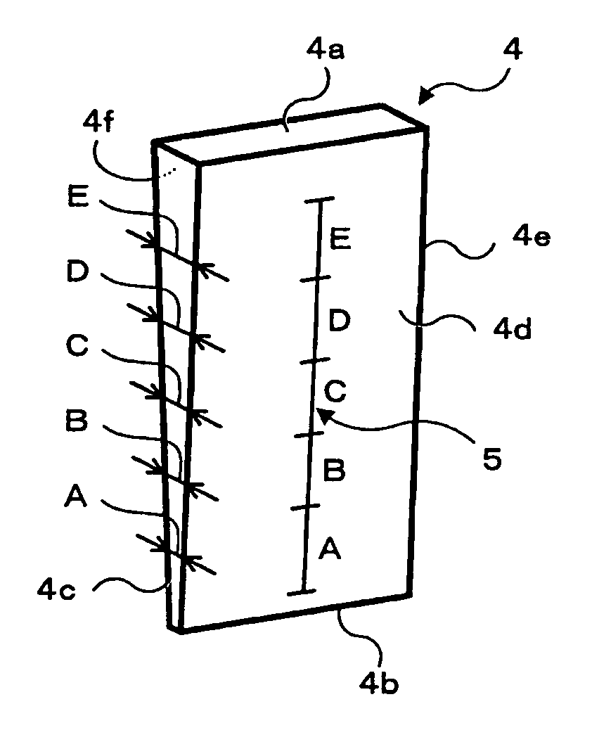
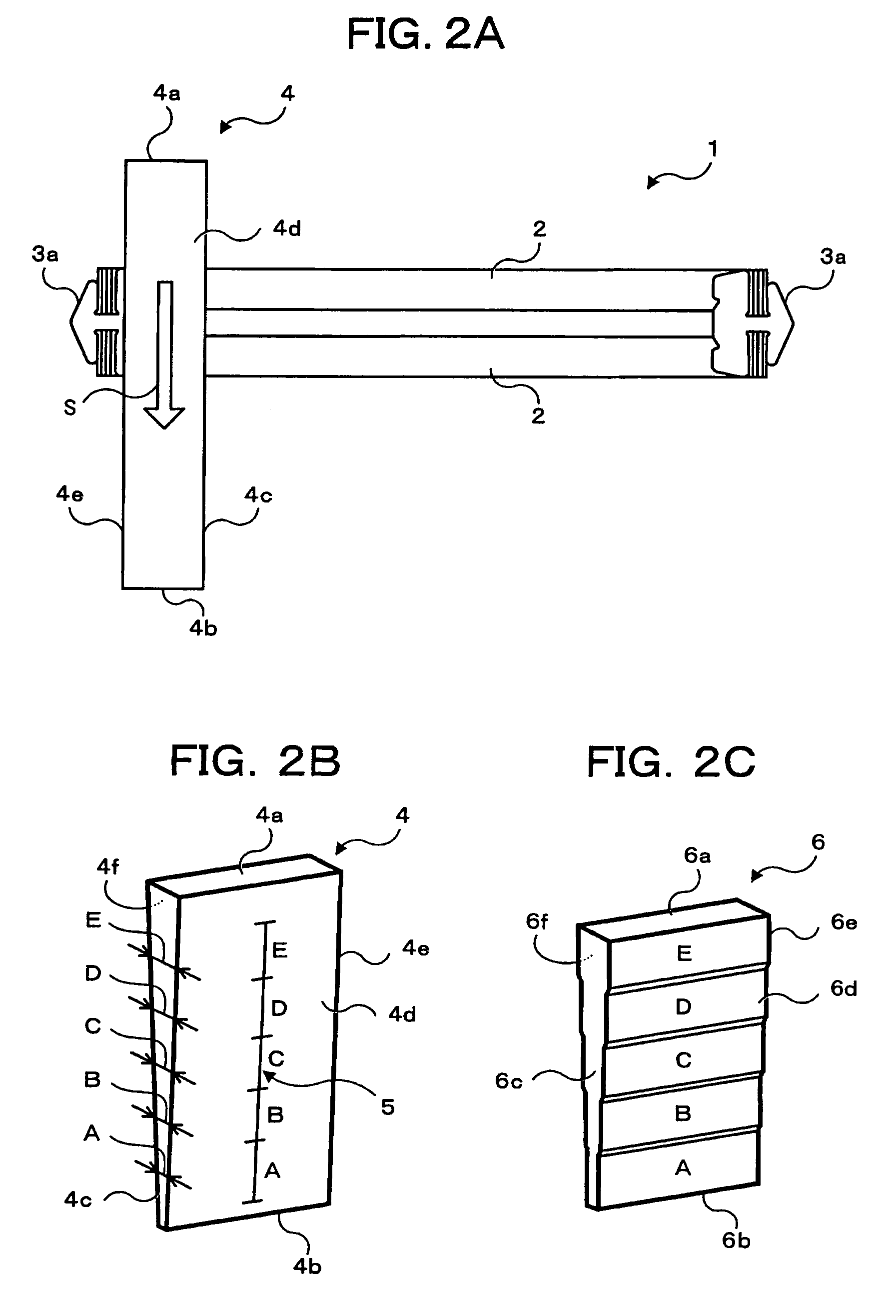
[0019]According to the present invention, a particular clearance value can be inspected quantitatively by examining whether or not the inspection jig is inserted in the clearance between metal elements by a predetermined force and how much of the wedge-shaped portion is inserted. Consequently, unlike the conventional prior art, this inspection jig eliminates the need for exchanging feeler gauge measuring blades repeatedly one by one and the clearance between metal elements is more easily measured in a onetime operation.
[0021]Moreover, according to the preferred embodiments of the present invention, the heretofore manual task of measuring the clearance between metal elements can be automated.
[0022]Finally, according to the preferred embodiments of the present invention, in particular because collapsing (topple over) of the metal elements positioned on both sides of the clearances between the metal elements is prevented, the time inconvenience in measuring wide clearances equivalent to the layered width of a several or many of the metal elements can also be avoided.

Problems solved by technology

Thus, it is necessary to measure clearances by constantly exchanging blade sizes which not only wastes time and effort but makes this an annoying problem.

Method used


Image

  • Continuously variable transmission belt inspection device
  • Continuously variable transmission belt inspection device
  • Continuously variable transmission belt inspection device

Examples


Embodiment Construction

[0031]The preferred embodiments of the present invention will hereinafter be described in detail with reference to the drawings. Additionally, illustration of specific or example numerical values for various details in the following explanation or character strings and other symbols are merely references to clarify the concept of the present invention. Accordingly, the concept of the present invention should not be limited explicitly to this terminology entirely or in part.

[0032]In addition, explanation is omitted which describes details of well-known methods, well-known procedures, well-known architecture, well-known circuit configurations, etc. (hereinafter denoted as “common knowledge”) for the purpose of concise explanation, but does not intentionally exclude this common knowledge entirely or in part. Therefore, relevant common knowledge already known by persons skilled in the art at the time of filing the present invention is naturally included in the following description.

[003...


PUM


Abstract

An inspection device designed for a large number of consecutively attached metal elements punched and processed into a specified shape and for inspecting clearance between said metal elements of a continuously variable transmission belt which are assembled to support a laminated band of a metal stepless belt; a wedge-shaped inspection jig, for example, used for inspecting quantitatively the clearance value with an inspection jig structure of a modified hexahedron having six surfaces containing an upper surface and a lower surface opposing four side surfaces of which both of two side surfaces are a rectangle and the remaining two side surfaces are a wedge-shape which becomes gradually narrower in width from an upper part to a lower part.

Description

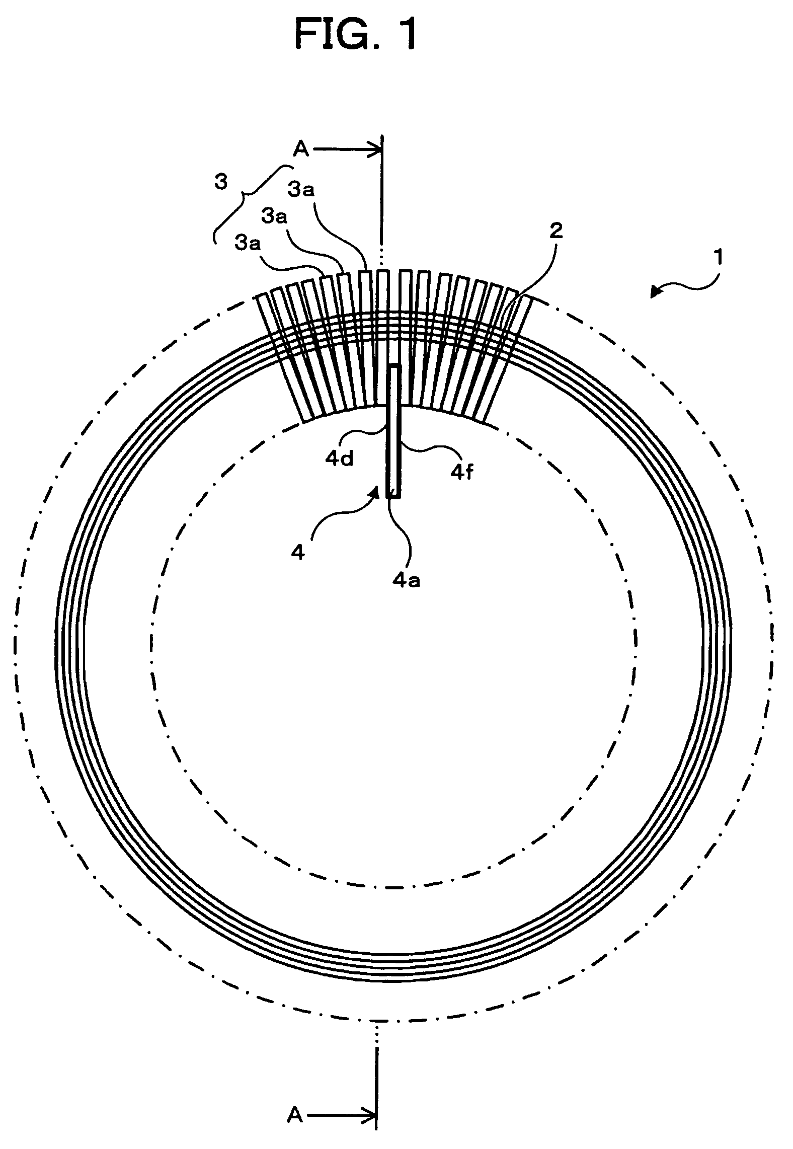
BACKGROUND OF THE INVENTION[0001]1. Field of the Invention[0002]The present invention relates to Continuously Variable Transmission (CVT) belt inspection device, and more particularly relates to a CVT belt inspection device designed for a large number of stacked layer metal elements punched and processed into a specified shape and assembled to support a laminated band of a metal stepless belt (hereinafter denoted as “steel belt”)[0003]2. Description of the Related Art[0004]FIG. 6 is an outline view of a CVT belt. In this diagram, a CVT belt 1 is constructed by assembling two belt laminated bands 2 composed of a plurality of steel belt bands (for example, a laminated band composed of about 12 endless belt layers) which are supported by consecutively attached elements 3 composed of a large number of metal elements 3a (for example, about 400 steel elements).[0005]FIG. 7 is an enlarged view of a metal element 3a. The metal element 3a consisting of a cast steel block (small piece of meta...

Claims


Application Information

Patent Timeline
Patent Type & Authority Patents(United States)
IPC IPC(8): G01B3/30F16G1/26F16G5/16F16H7/24G01B5/14G01M13/02
CPCG01B3/306
Inventor TANGE, HIROSHI
Owner JATCO LTD
Why Eureka
Try Eureka