Molecular filter dehumidification apparatus and plant

Active Publication Date: 2007-03-13
MORETTO SPA
View PDF8 Cites 26 Cited by
  • Summary
  • Abstract
  • Description
  • Claims
  • Application Information

AI Technical Summary

Benefits of technology

[0016]The main object of the present invention is to provide a molecular sieve dehumidification device and a plant of a new conception suitable for eliminating or considerably reducing the above mentioned limitations to be found with the dehumidification towers known in the state of the art.
[0017]Another object of the present invention is to provide a safe and efficient molecular sieve dehumidification device and plant suitable for providing a high efficiency operation.
[0018]A further object of the present invention is to provide a molecular filter dehumidification device and plant which is relatively simple to manufacture and install so as to be advantageous also from the economical point of view.

Problems solved by technology

The elimination of the humidity content of the granules is necessary because during the high temperature fusion of the material the water penetrates into the molecular chain of the polymer granulate and breaks it, which results in a reduction of mechanical performance and generates bubbles, pitting and uneven colouring of the product.
The adsorption capacity of the filters is however quantitatively limited and after a certain time saturation is reached.
Clearly, in order to regenerate conventional filter cartridges or towers a considerable amount of energy and time are required.
Most of the energy consumption in such towers is due to production of the heat required for regenerating the sieves.
A serious operating problem of conventional dehumidifiers is the fact that such configurations are “orthogonal”, i.e. air is always conveyed along preferential routes in the sieves mass MS caused by the dynamics of the fluid in the tower.
This means that it is impossible to exploit entirely the totality of the molecular sieve mass and hence one does not take full advantage of the potential of the tower, although one consumes a greater amount of energy than necessary, which considerably reduces the efficiency as a whole.

Method used


Image

  • Molecular filter dehumidification apparatus and plant
  • Molecular filter dehumidification apparatus and plant
  • Molecular filter dehumidification apparatus and plant

Examples


Embodiment Construction

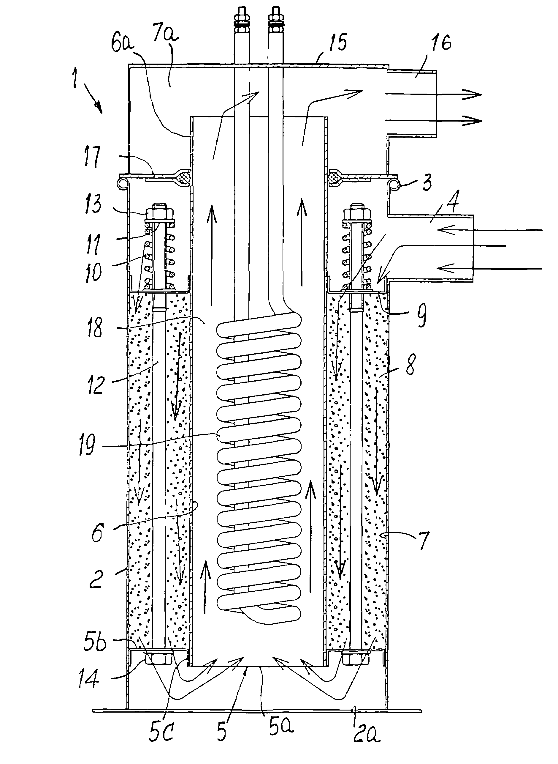
[0032]With reference first to FIG. 3, it will be seen that a dehumidification tower 1 according to the present invention comprises an outer container or jacket 2 having a bottom 2a, preferably cylindrical in shape and made of stainless steel. In the vicinity of its upper end 3 which is preferably curled as will be further explained below, the outer jacket or container 2 is equipped with an air intake / outlet opening or duct 4, as explained below.

[0033]At a short distance from the bottom 2a within the container 2 there is fixed, preferably by welding, a first or lower grid 5, which extends at two different levels, i.e. it has a central portion 5a substantially parallel to the bottom 2a and a peripheral (circular) crown portion 5b higher than the central portion 5a so as to delimit an inner vertical axial shoulder 5c.

[0034]An inner tubular metal sleeve 6, preferably made of stainless steel, is inserted into shoulder 5c, and extends in the longitudinal axial direction. Between outer co...


PUM

PropertyMeasurementUnit
Lengthaaaaaaaaaa
Flow rateaaaaaaaaaa
Massaaaaaaaaaa

Abstract

A dehumidification apparatus including an outer tubular container (2) closed at its ends, a first (5) and a second (9) transverse grids located inside the tubular container (2), one grid element being spaced from the other and from a respective adjacent end of the tubular container (2) and delimiting a receiving space therewith, a mass of molecular sieves (MS) located in the receiving space, heating elements (19) in the tubular container (2), and first and second openings (4, 16) for communication of the interior of the container with the outside, characterised in that it comprises an inner tubular jacket (6) extending from at least the first grid (5) for a distance greater than that between the first (5) and the second (9) grid, thereby shaping the receiving space for the sieves (8) as an annular gap and providing a projecting section (6a) extending from the second grid (9); and an annular partition (17) between the outer container (2) and the inner jacket (6) at the projecting section (6a) of the inner jacket (6), thereby delimiting an annular manifold space (7) with the second grid element (9) communicating with the outside through the first opening (4), and an end space (7a) adjacent to the second end of the external container (2) communicating with the interior (18) of the inner jacket (6) and with the outside through the second opening (16).

Description

FIELD OF THE INVENTION[0001]The present invention regards a molecular filter dehumidification apparatus and plant.BACKGROUND OF THE INVENTION[0002]As is known in the transformation of plastic materials, a very important treatment is the process of dehumidification of the plastic material granules, in other words the removal of the water contained in the granules of so-called hygroscopic plastics.[0003]The elimination of the humidity content of the granules is necessary because during the high temperature fusion of the material the water penetrates into the molecular chain of the polymer granulate and breaks it, which results in a reduction of mechanical performance and generates bubbles, pitting and uneven colouring of the product.[0004]Traditional equipment for dehumidifying or separating and eliminating the water from the plastic granules are commonly known as dehumidifiers. In the majority of cases, a dehumidifier is a machine employing the principle of molecular filters. In prac...

Claims


Application Information

Patent Timeline
IPC IPC(8): F26B21/06F26B21/08
CPCF26B21/083B01D53/261B01D53/0407B29B9/16B29B13/065
Inventor MORETTO, RENATO
Owner MORETTO SPA
Why Eureka
Try Eureka