Coaxial cable fitting and crimping tool

a technology of crimping tool and coaxial cable, which is applied in the field of crimping devices to achieve the effect of reliable and efficien

Inactive Publication Date: 2007-03-13
PPC BROADBAND INC
View PDF11 Cites 42 Cited by
  • Summary
  • Abstract
  • Description
  • Claims
  • Application Information

AI Technical Summary

Benefits of technology

[0004]It is therefore an object to provide for a novel and improved crimping tool conformable for use in compressing different sizes and lengths of fittings onto the end of a cable in a reliable and efficient manner.
[0005]Another object is to provide for a novel and improved hand-held crimping tool for crimping fittings into sealed engagement with a coaxial cable without requiring a preassembled crimping ring but is capable of achieving a uniform seal notwithstanding differences in length of the fitting, or to compensate for the presence of wear or dirt and differences in manufacturing tolerances.
[0006]A further object is to provide for a novel and improved hand-held crimping tool for terminating cable ends without the use of a preassembled crimping ring which greatly facilitates both mounting and release of the cable end before and after the crimping operation and wherein the tool is lightweight but sturdy and requires a minimum number of parts.
[0011]Another feature is that different sets of die members can be interchangeably mounted in the die housing according to the size and length of fitting to be crimped onto the cable end, and each set of die members defines a cavity having a first diameter corresponding to an outer diameter of the sleeve portion and a second diameter which corresponds to the outer diameter of the cable end. The housing itself is characterized by having inclined guideways on opposite sides of the housing to advance the die members between the expanded and contracted positions. The inclined guideways include end portions which increase the compressive force exerted by the die members on the sleeve portions in completing the crimping operation and are self-compensating for any manufacturing variance or wear of the die cavities and guide portions of the die members.

Problems solved by technology

In the past, however, when the die portions have been mounted on the body of the tool they are difficult to open when the fitting becomes jammed; also the ability of the die halves to resist misalignment when subjected to crimping forces; and the ability of the tool to be self-adjusting for wear tolerances and other slight differences in size and length of each fitting or connector have presented problems in the field.

Method used


Image

  • Coaxial cable fitting and crimping tool
  • Coaxial cable fitting and crimping tool
  • Coaxial cable fitting and crimping tool

Examples


Embodiment Construction

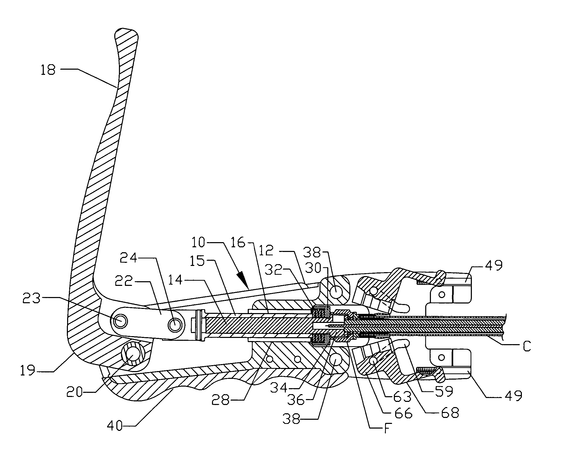
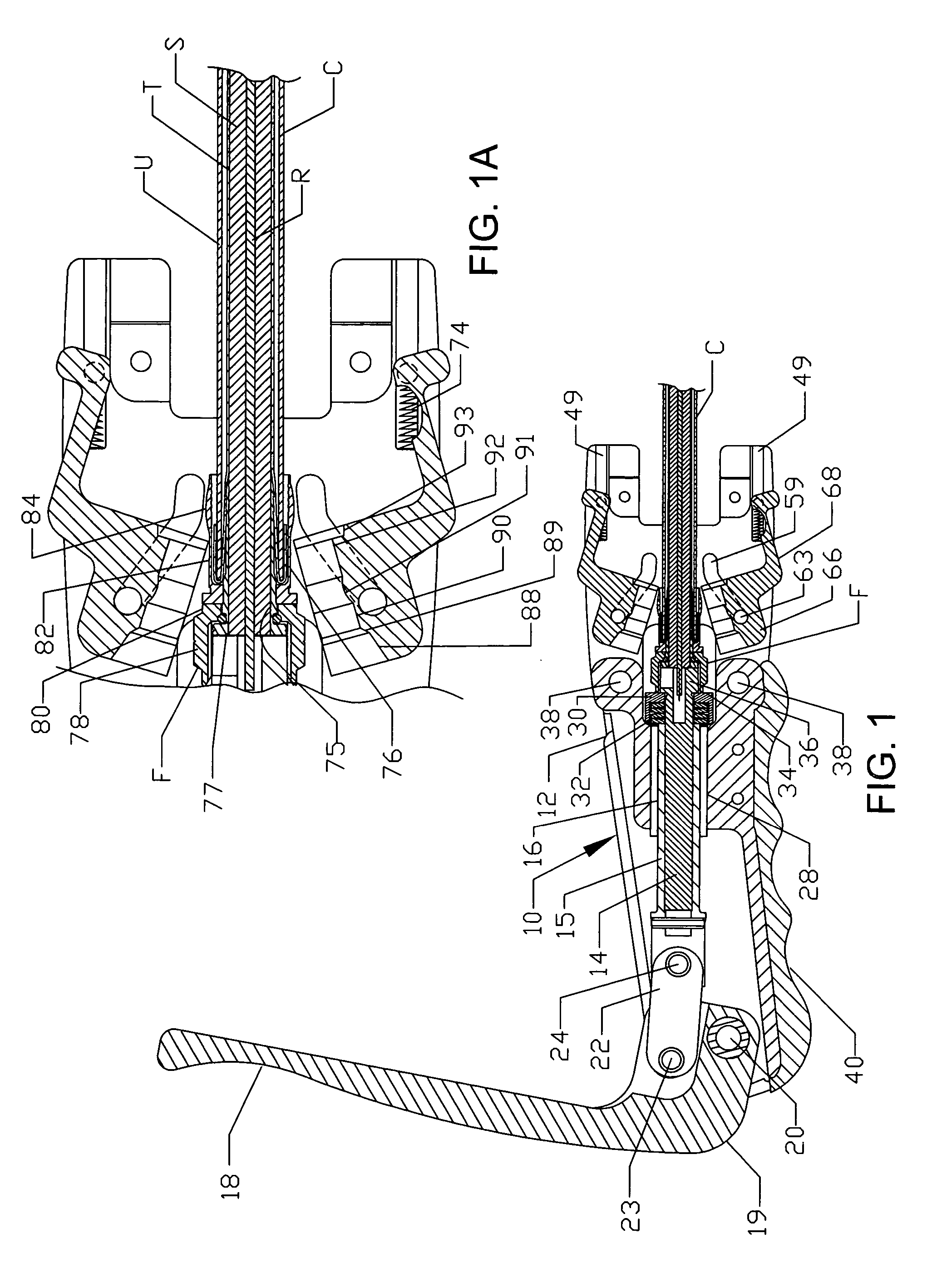
[0024]Referring in more detail to the drawings, one form of handheld crimping tool 10 is shown in FIGS. 1 through 6 and is broadly comprised of an elongated body 12 of generally channel-shaped configuration, as best seen from FIGS. 3 and 5. A plunger 15 extends through a plunger-receiving bore 16 in the body, and a lever arm 18 has an offset end portion 19 pivotally mounted in the channel at the rear end of the body 12. A floating link 22 is pivotally attached at 23 in offset relation to the pivot 20 and pivotally attached at its opposite end 24 to an end of the plunger 14. Further, the lever arm 18 is of a width substantially corresponding to the width of the channel in the body 12 so as to be free to pivot from the extreme raised or upright position shown in FIG. 1 to the substantially horizontal position overlying the body 12, as shown in FIG. 2. The plunger 14 is slidable through bushing 28 in the bore 16 and terminates in a large hollow housing 30 for a spring stack 32. A sleev...


PUM

PropertyMeasurementUnit
resilientaaaaaaaaaa
diameteraaaaaaaaaa
inner diameteraaaaaaaaaa

Abstract

A crimping tool for connecting a cable fitting to the end of a cable is made up of an elongated body having a lever arm pivoted at one end of the body to actuate a plunger having a chuck at one end toward and away from axially slidable die portions on the body, and the die portions can be expanded to permit insertion of the connector sleeve and cable into engagement with the end of the chuck and contracted to apply a uniform crimping force to the fitting in response to an axial force applied to the chuck to increase the crimping force causing the die portions to be further contracted into crimping engagement following which the die portions can be expanded to release the fitting and cable from the tool.

Description

BACKGROUND AND FIELD OF INVENTION[0001]This invention relates to crimping devices, and more particularly relates to a novel and improved hand-held universal crimping tool for crimping fittings of different lengths into sealed engagement with cables, such as, for example, coaxial cables employed in the cable TV industry.[0002]Hand-held crimping tools have been devised for crimping a connector onto the end of a coaxial cable and which are characterized in particular by being capable of reducing the diameter of the fitting into a generally circular configuration in response to an axially directed force to the fitting. Representative of these inventions are U.S. Pat. No. 5,392,508 for AXIAL DEFORMATION CRIMPING TOOL and U.S. Pat. No. 6,293,004 for LENGTHWISE COMPLIANT CRIMPING TOOL, both of said patents being owned by the assignee of this invention and incorporated by reference herein, the latter being characterized in particular by having a spring-loaded chuck on the end of a plunger w...

Claims


Application Information

Patent Timeline
Patent Type & Authority Patents(United States)
IPC IPC(8): H01R43/042
CPCB21D39/048Y10T29/53987Y10T29/53226Y10T29/53996
Inventor HOLLIDAY, RANDALL A.PARKER, ROBERT M.
Owner PPC BROADBAND INC
Why Eureka
Try Eureka