
Turbomachine

a technology of rotating parts and rotating plates, applied in the field of rotating parts, can solve problems such as static axial bearings

Inactive Publication Date: 2007-03-13
ATLAS COPCO ENERGAS
View PDF4 Cites 0 Cited by
  • Summary
  • Abstract
  • Description
  • Claims
  • Application Information

AI Technical Summary

Benefits of technology

[0006]It is an object of the present invention to provide a turbomachine having the characteristics described initially, which allows a design and construction of the hydrodynamic axial bearing that is optimally coordinated with the operating conditions at the rated speed of rotation.
[0007]These and other objects are achieved, according to the invention, by additionally providing a hydrostatic axial bearing in the immediate vicinity of the hydrodynamic bearing. The hydrostatic axial bearing absorbs the axial force acting on the rotor shaft at rest, completely or at least for the most part, relieves stress on the hydrodynamic axial bearing during start-up processes, and is shut off during operation at the rated speed of rotation.
[0008]According to the invention, a division of the components that absorb the axial thrust takes place. The components are divided into a static part that absorbs the axial force acting on the rotor shaft at rest and during start-up, completely or at least for the most part, and a hydrodynamic part whose design and construction can be optimally coordinated with the conditions that prevail during operation at the rated speed of rotation. This arrangement particularly allows a reduction in the dissipated energy of the hydrodynamic axial bearing at rated operation, as well as dimensioning of the hydrodynamic axial bearing that is optimally coordinated with the axial thrusts that occur at rated operation. At rest and during the start-up process, the hydrodynamic axial bearing is relieved of stress, to a great extent, by the additional hydrostatic axial bearing. When the rotor shaft has reached its rated speed of rotation, the static axial bearing is shut off, and thereby becomes ineffective, and the axial thrust is completely absorbed by the hydrodynamic axial bearing.
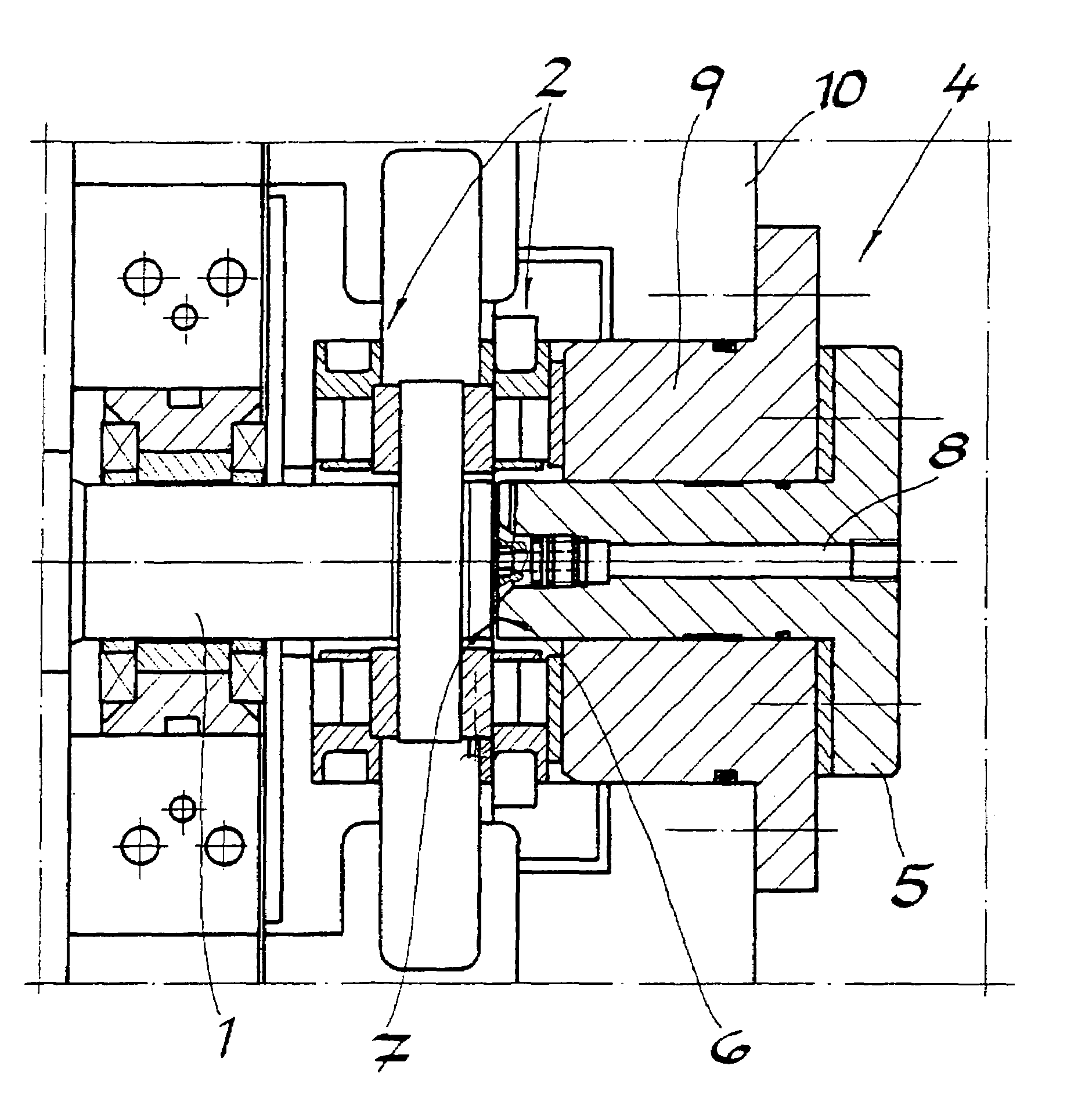
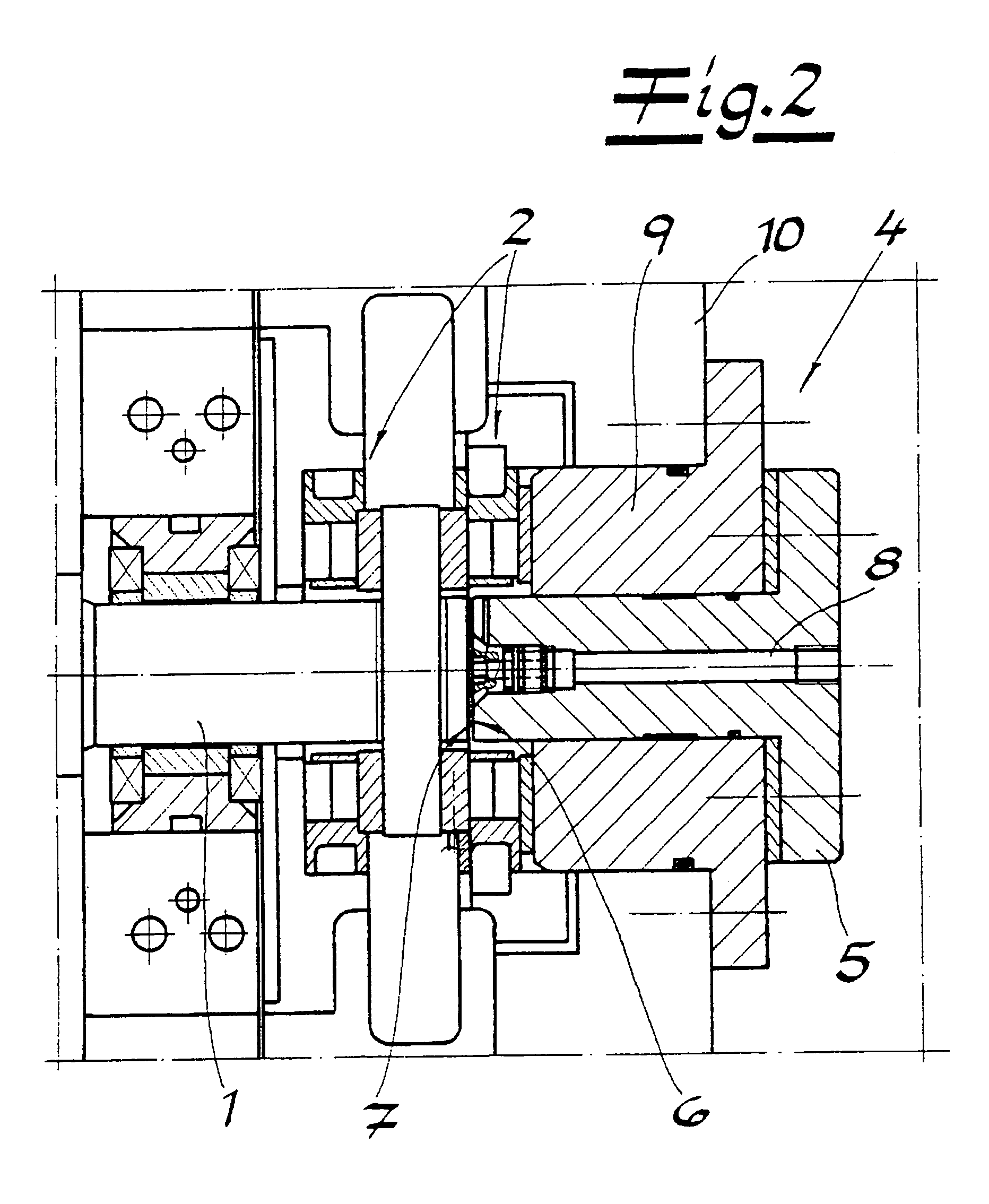
[0009]Preferably, the two axial bearings are disposed at a free end of the rotor shaft. It is practical if the hydrostatic axial bearing has a fixed piston that absorbs the axial forces, whose face is directed at the face of the corresponding rotor shaft end, whereby a bearing fluid that is under pressure is located between the two faces while the rotor shaft is at rest and during the start-up process, which fluid separates the two surfaces, putting them at a distance from one another. It is advantageous if the distance between the two surfaces is approximately 50 μm, whereby a deviation of 10 μm up or down is acceptable. The piston, which is configured as an insert, can have a bore for the supply of the bearing fluid into the interstice between the two faces. Preferably, the piston is inserted into a sleeve and connected therewith. The sleeve is attached to a housing of the turbomachine and transfers the axial forces absorbed by the piston to the housing. The end of the sleeve that faces the rotor shaft simultaneously serves to introduce the axial forces transferred by the hydrodynamic axial bearing into the housing.

Problems solved by technology

When the rotor shaft has reached its rated speed of rotation, the static axial bearing is shut off, and thereby becomes ineffective, and the axial thrust is completely absorbed by the hydrodynamic axial bearing.

Method used


Image

  • Turbomachine
  • Turbomachine
  • Turbomachine

Examples


Embodiment Construction

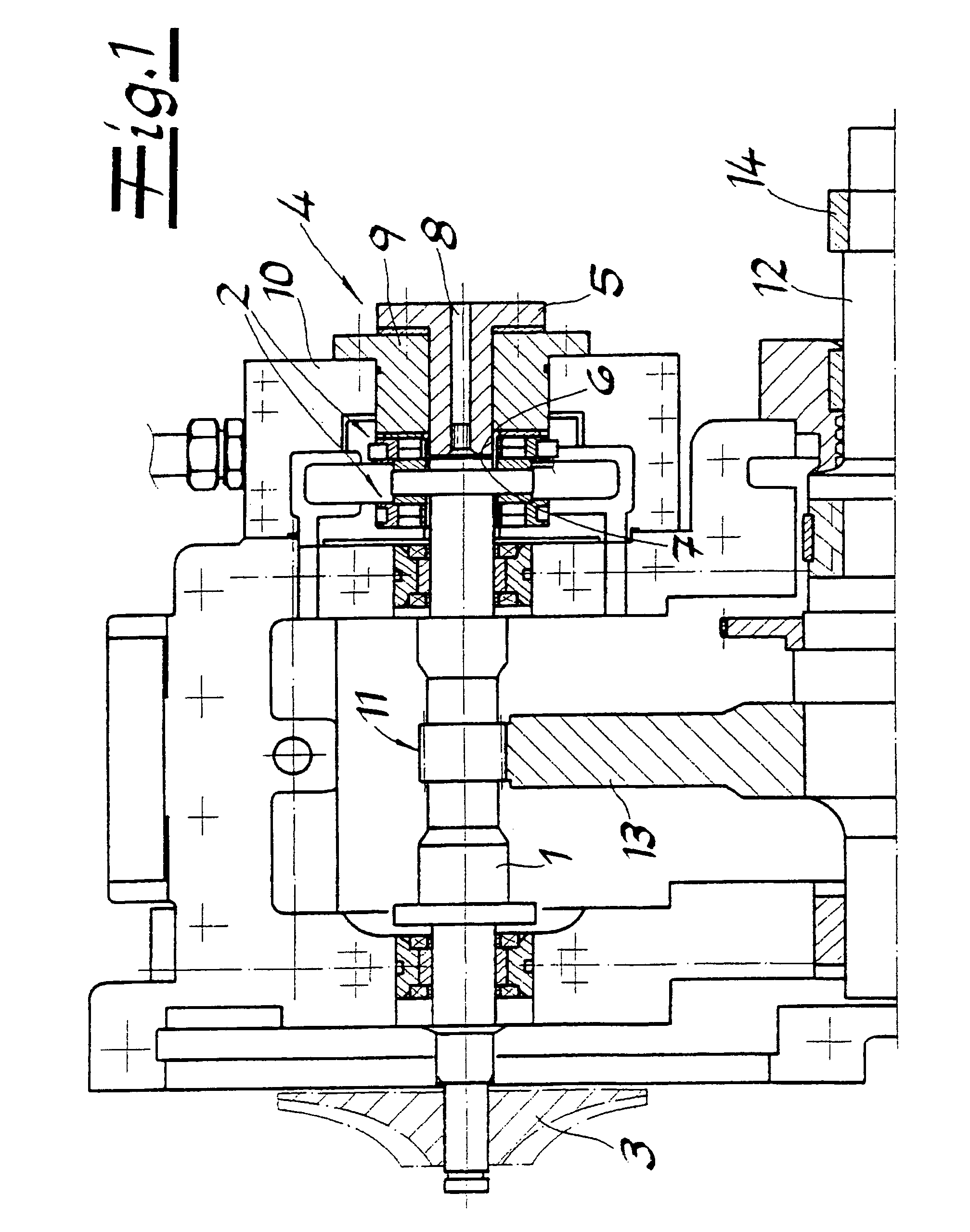
[0015]Referring now to the drawings, FIG. 1 shows a turbomachine configured as a compressor, having a rotor shaft 1. Rotor shaft 1 is mounted in a bearing arrangement containing a hydrodynamic axial bearing 2. At one end of rotor shaft 1, a compressor rotor 3 is disposed in cantilevered manner.

[0016]In the immediate vicinity of hydrodynamic axial bearing 2, a hydrostatic axial bearing 4 is additionally provided. Hydrostatic axial bearing 4 absorbs the axial force that acts on rotor shaft 1 when it is at rest, completely or at least for the most part. During start-up processes of rotor shaft 1, stress on hydrodynamic axial bearing 2 is relieved by axial bearing 4, while axial bearing 4 is shut off during operation at the rated speed of rotation. The two axial bearings 2, 4 are disposed on the remaining free end of rotor shaft 1. It is particularly evident from FIG. 2 that hydrostatic axial bearing 4 has a fixed piston 5 that absorbs the axial forces, the face 6 of which is directed a...


PUM


Abstract

A turbomachine has a rotor shaft, which is mounted in a bearing arrangement containing a hydrodynamic axial bearing, and a rotor disposed on the rotor shaft. A hydrostatic axial bearing is additionally provided in the immediate vicinity of the hydrodynamic axial bearing, the hydrostatic axial bearing absorbing the axial force acting on the rotor shaft at rest, completely or at least for the most part, relieving stress on the hydrodynamic axial bearing during start-up processes of the rotor shaft, and being shut off during operation at the rated speed of rotation.

Description

CROSS REFERENCE TO RELATED APPLICATIONS[0001]Applicants claim priority under 35 U.S.C. §119 of German Application No. 10 2004 023 149.4 filed May 7, 2004.BACKGROUND OF THE INVENTION[0002]1. Field of the Invention[0003]The present invention relates to a turbomachine having a rotor shaft, which is mounted in a bearing arrangement containing a hydrodynamic axial bearing, and having a rotor disposed on the rotor shaft. The term “hydrodynamic axial bearing” refers to commercially available axial slide bearings that are frequently used in turbomachine construction.[0004]2. The Prior Art[0005]In known turbomachines known having the characteristics described initially, the hydrodynamic axial bearing serves two purposes. The hydrodynamic axial bearing serves both to absorb the axial forces that occur when the rotor shaft is not moving, and to absorb the axial thrusts that occur during operation of the turbomachine. The axial thrusts depend on the pressure conditions at the rotor, the type of...

Claims


Application Information

Patent Timeline
Patent Type & Authority Patents(United States)
IPC IPC(8): F16C32/06F04D29/056F01D25/16F04D25/16F04D29/04F04D29/28F16C17/04F16C17/20
CPCF01D25/168F04D25/163F16C17/04F04D29/0513F16C32/0692F16C39/04F16C17/20F05D2240/53F16C2360/44
Inventor SOPPER, ALFREDLEONHARD, MARTIN
Owner ATLAS COPCO ENERGAS
Learn More