Burner with staged fuel injection

a fuel injection and burner technology, applied in the direction of combustion types, combustion using lump and pulverulent fuel, lighting and heating apparatus, etc., can solve the problems of increasing no/sub>x /sub>emission, insufficient intermixing of combustion air, and virtually impossible to meet all these requirements by means of a fixed distribution of outlet orifices

Inactive Publication Date: 2007-03-13
ANSALDO ENERGIA IP UK LTD
View PDF42 Cites 10 Cited by
  • Summary
  • Abstract
  • Description
  • Claims
  • Application Information

AI Technical Summary

Benefits of technology

[0018]By virtue of this configuration of the present burner, a higher pulsation becomes possible, even when the plant is under low load, that is to say in the case of a low burner power and low overall adiabatic combustion temperatures. The inventors have recognized, in this context, that, when the first stage is operated without a separating element of this type, on the one hand, the flame can execute relatively free axial pulsations and, on the other hand, these pulsations are assisted by virtue of the cooling effect of the combustion air flowing in through the air inlet orifices in the region of the second stage. By the separating element being inserted between the air streams which flow into the swirl space in the region of the first stage and the air streams which flow in in the region of the second stage, an interaction between these air streams in the case of a low burner power can be prevented. This, in turn, advantageously leads to a reduction in the combustion pulsations.
[0019]In an advantageous embodiment, the burner comprises a fuel lance which extends into the region of the separating element or of the volume formed by the separating element. This burner lance is thus prolonged, as compared with the fuel or piloting lances known from the prior art, in conjunction with the burners with single-stage fuel injection. By the fuel lance being prolonged in this way into the volume of the separating element, an additional stabilizing point for the fuel / air mixture by means of the “stage jump” via the lance tip of the first stage is provided, and the axial combustion pulsation is further reduced.
[0021]The separating element is exemplarily produced integrally with the swirl body or with the shells forming the latter or is fastened thereto. This exemplary embodiment of the burner makes it possible to provide existing burner constructions with the separating element without complicated reconstruction.

Problems solved by technology

Piloting, however, leads to increased NOx emissions, since, in this operating mode, only insufficient intermixing with the combustion air can take place.
In this case, it is virtually impossible to fulfil all these requirements by means of a fixed distribution of the outlet orifices, even under changing operating and ambient conditions.
A further disadvantage of the known methods for the operation of premixing burners is that these are optimized for low emissions and low combustion oscillations under full-load conditions.
In order to start up the burner and start the gas turbine, an additional piloting stage is required, which, however, causes the emission values to rise markedly.
The burners, developed by the applicant, with multistage fuel injection by the division of the fuel supplies into two separate regions show, in particular, a reduction in the NOx emissions and in the intensity of the combustion pulsations at higher flame temperatures above 1650 K. However, the problem of pulsations still arises at temperatures below 1500 K when the first stage is operated essentially alone and therefore performs a function similar to that of a piloting stage.

Method used


Image

  • Burner with staged fuel injection
  • Burner with staged fuel injection

Examples


Embodiment Construction

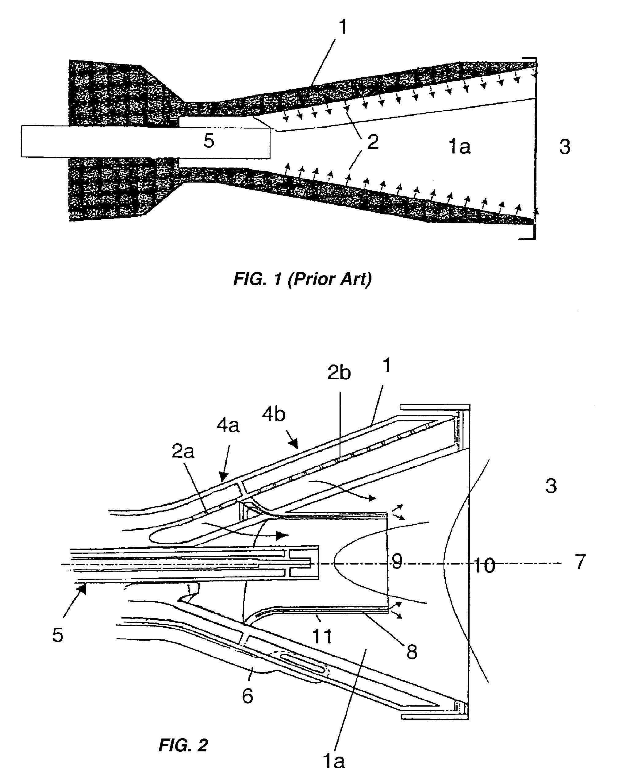
[0025]FIG. 1 shows a single-stage burner system, such as is known from the prior art and has already been explained in the description introduction.

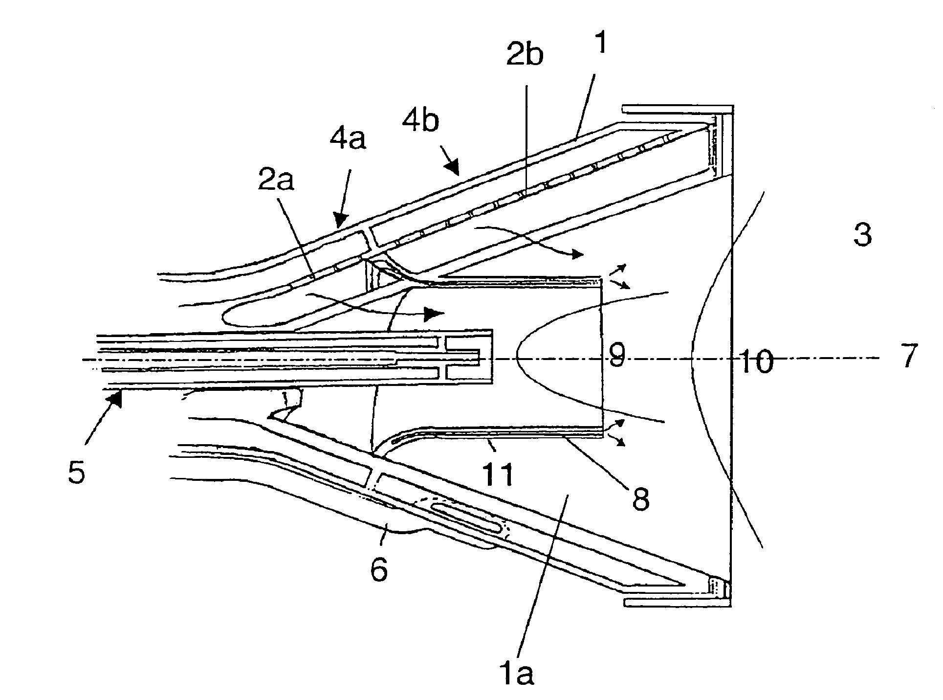
[0026]In the present exemplary embodiment, a burner geometry is used, such as is known, in principle, from the prior art initially mentioned, in particular from EP 0 321 809 B1. The burner consists of the swirl body 1 which comprises a swirl space 1a for intermixing the fuel with the combustion air (indicated by arrows) entering the swirl body 1 via air inlet slits. The swirl space 1a is followed by the combustion chamber 3. The swirl generator 1 is designed conically in a known way and consists of a plurality of part shells. The ductlike supplies 4a and 4b for injecting the fuel into the swirl space 1a are arranged in these part shells. In the present burner system, two-stage fuel injection is used, in which a first stage is formed by the fuel supply 4a and a second stage by the fuel supply 4b. In this context, the figure shows diagramm...


PUM


Abstract

A burner with staged fuel injection includes at least two separate stages (4a, 4b) for fuel injection arranged along the swirl body (1). The burner is distinguished in that, between the first and the second stage (4a, 4b), a separating element (8) is provided, which extends in the direction of the combustion chamber (3) and separates the combustion air flow which enters in the region of the first stage (4a) from the combustion air flow which enters in the region of the second stage (4b). The burner can be operated with low combustion pulsations even in the case of low burner powers.

Description

[0001]This application is a Continuation of, and claims priority under 35 U.S.C. § 120 to, U.S. application Ser. No. 10 / 398,374, filed 9 Oct. 2003, “Burner with Staged Fuel Injection”, by the inventors hereof (now abandoned), which was a U.S. National Stage application under 35 U.S.C. § 371 of International Application Number PCT / IB01 / 01817, filed 3 Oct. 2001, published as WO 02 / 33324 in German, and claims priority under 35 U.S.C. § 119 to German application number 100 51 221.6, filed 16 Oct. 2000, the entireties of all of which are incorporated by reference herein.BACKGROUND OF THE INVENTION[0002]1. Field of the Invention[0003]The present invention relates to a burner with staged fuel injection, which is composed of a swirl generator for a combustion air stream and means for the introduction of fuel into the combustion air stream, the means for the introduction of fuel into the combustion air stream comprising at least one first fuel supply with a first group of fuel outlet orifice...

Claims


Application Information

Patent Timeline
Patent Type & Authority Patents(United States)
IPC IPC(8): F23D14/24F23D14/78F23D11/12F23D14/22F23R3/12F23R3/28F23R3/34
CPCF23R3/286F23R3/12
Inventor PENNELL, DOUGLASEROGLU, ADNAN
Owner ANSALDO ENERGIA IP UK LTD
Why Eureka
Try Eureka