Controller for controlling power generator driven by rotational power of engine

a technology of controller and power generator, which is applied in the direction of electric generator control, dynamo-electric converter control, dynamo-electric brake control, etc., can solve the problems of engine stall, engine deterioration, engine speed reduction, etc., and achieve the effect of reducing engine speed and deteriorating engine startability

Active Publication Date: 2014-07-08
DENSO CORP
View PDF15 Cites 12 Cited by
  • Summary
  • Abstract
  • Description
  • Claims
  • Application Information

AI Technical Summary

Benefits of technology

[0007]Specifically, an alternative aspect of the present disclosure aims to provide such controllers capable of improving the startability of an engine even if there are higher pulsations in rotation of the engine.
[0010]This configuration can determine that the measured rotation number of the rotor is reliably equal to or higher than the threshold rotation number. Thus, even if there are great pulsations of rotation of the engine, it is possible to shift the operation mode of the voltage controller from the initial excitation mode to the power generation mode after the measured rotation number of the rotor has been reliably equal to or higher than the threshold rotation number. This prevents a speed of the engine from dropping due to an increase of torque required for the power generation mode, thus improving the startability of the engine.

Problems solved by technology

The increase in the torque may further reduce the engine speed, resulting in a deterioration of the startability of the engine.
This deterioration in the engine may cause the engine to stall.

Method used


Image

  • Controller for controlling power generator driven by rotational power of engine
  • Controller for controlling power generator driven by rotational power of engine
  • Controller for controlling power generator driven by rotational power of engine

Examples


first modification

[0061]A controller according to the first modification of the embodiment of the present disclosure will be described with reference to FIGS. 4 and 5.

[0062]The structure and / or functions of the controller according to the first modification are different from those of the controller 1 by the following points. So, the different points will be mainly described hereinafter.

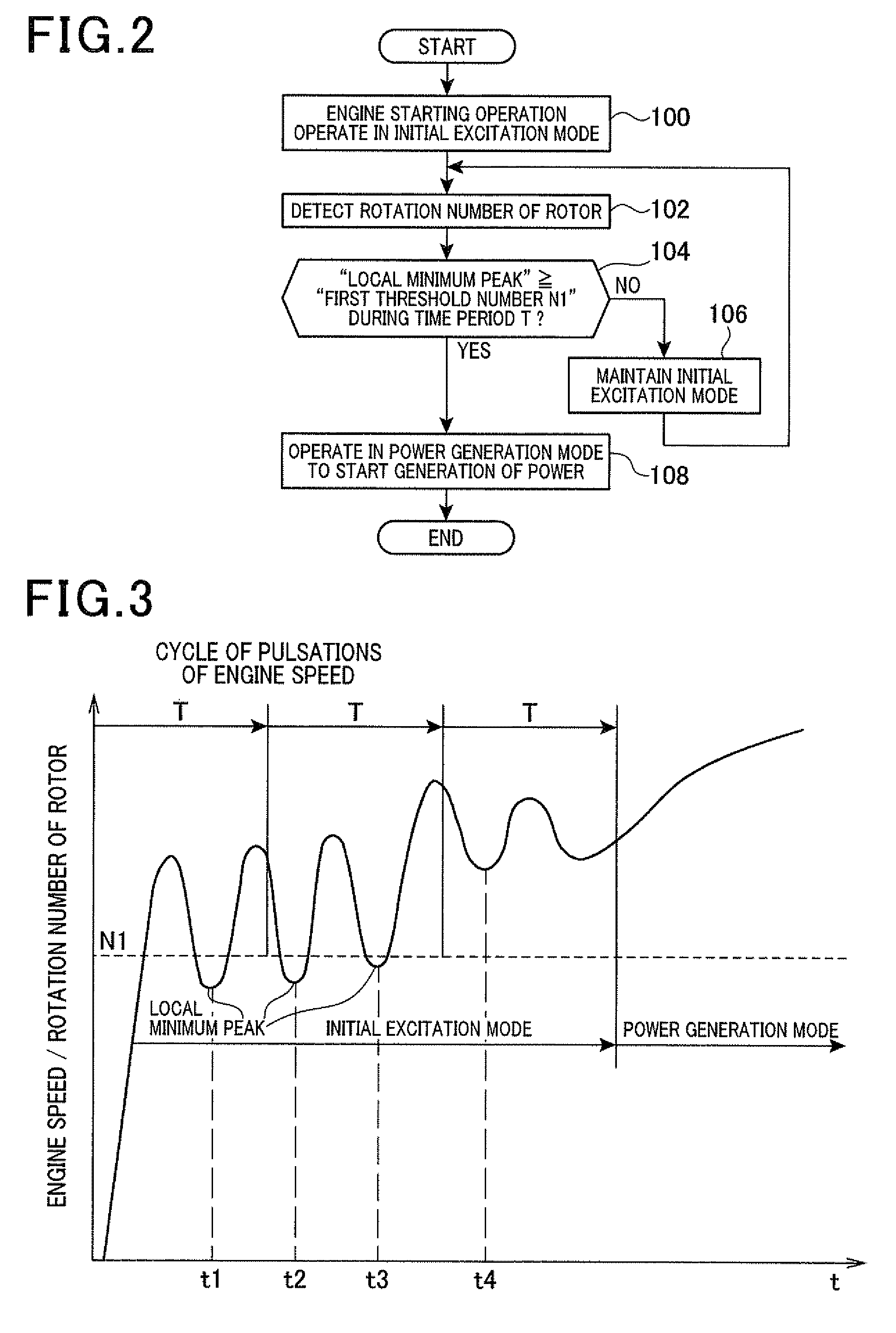
[0063]Operations of the controller according to the first modification for determination of start of generation of power during startup of the engine EN will be described hereinafter with reference to FIG. 4. In the flowcharts of FIGS. 2 and 4, like operations (steps), to which like reference step numbers are assigned, are omitted or simplified in redundant description.

[0064]Specifically, the controller according to the first modification is programmed to perform the following operations in steps 200 to 206 before the operation in step 100. Thus, the operations in steps 200 to 206 will be fully described hereinafter.

[...

second modification

[0072]A controller according to the second modification of the embodiment of the present disclosure will be described with reference to FIGS. 6 and 7.

[0073]The structure and / or functions of the controller according to the second modification are different from those of the controller 1 by the following points. So, the different points will be mainly described hereinafter.

[0074]Operations of the controller according to the second modification for determination of start of generation of power during startup of the engine EN will be described hereinafter with reference to FIG. 6. In the flowcharts of FIGS. 2 and 6, like operations (steps), to which like reference step numbers are assigned, are omitted or simplified in redundant description.

[0075]Specifically, the controller according to the second modification is programmed to perform the following operations in steps 300 to 304 between the operations in steps 102 and 104. Thus, the operations in steps 300 to 304 will be fully describe...

third modification

[0082]A controller according to the third modification of the embodiment of the present disclosure will be described with reference to FIG. 8.

[0083]The structure and / or functions of the controller according to the second modification are different from those of the controller 1 by the following points. So, the different points will be mainly described hereinafter.

[0084]Operations of the controller according to the third modification for determination of start of generation of power during startup of the engine EN will be described hereinafter with reference to FIG. 8.

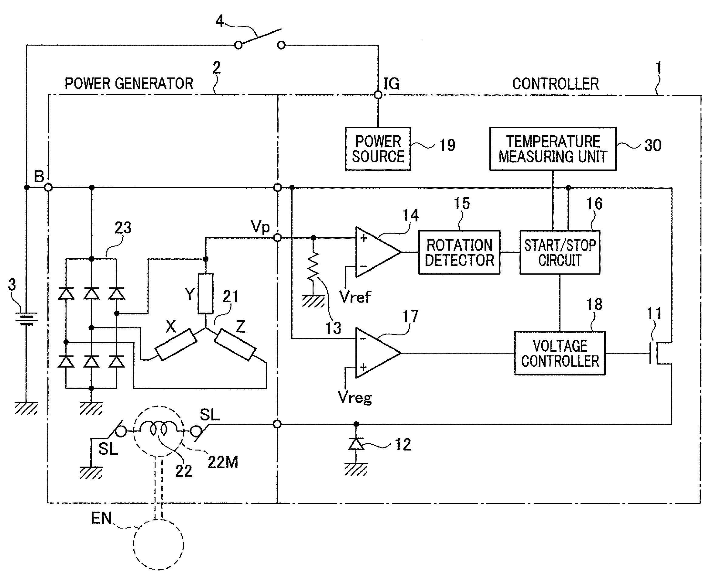
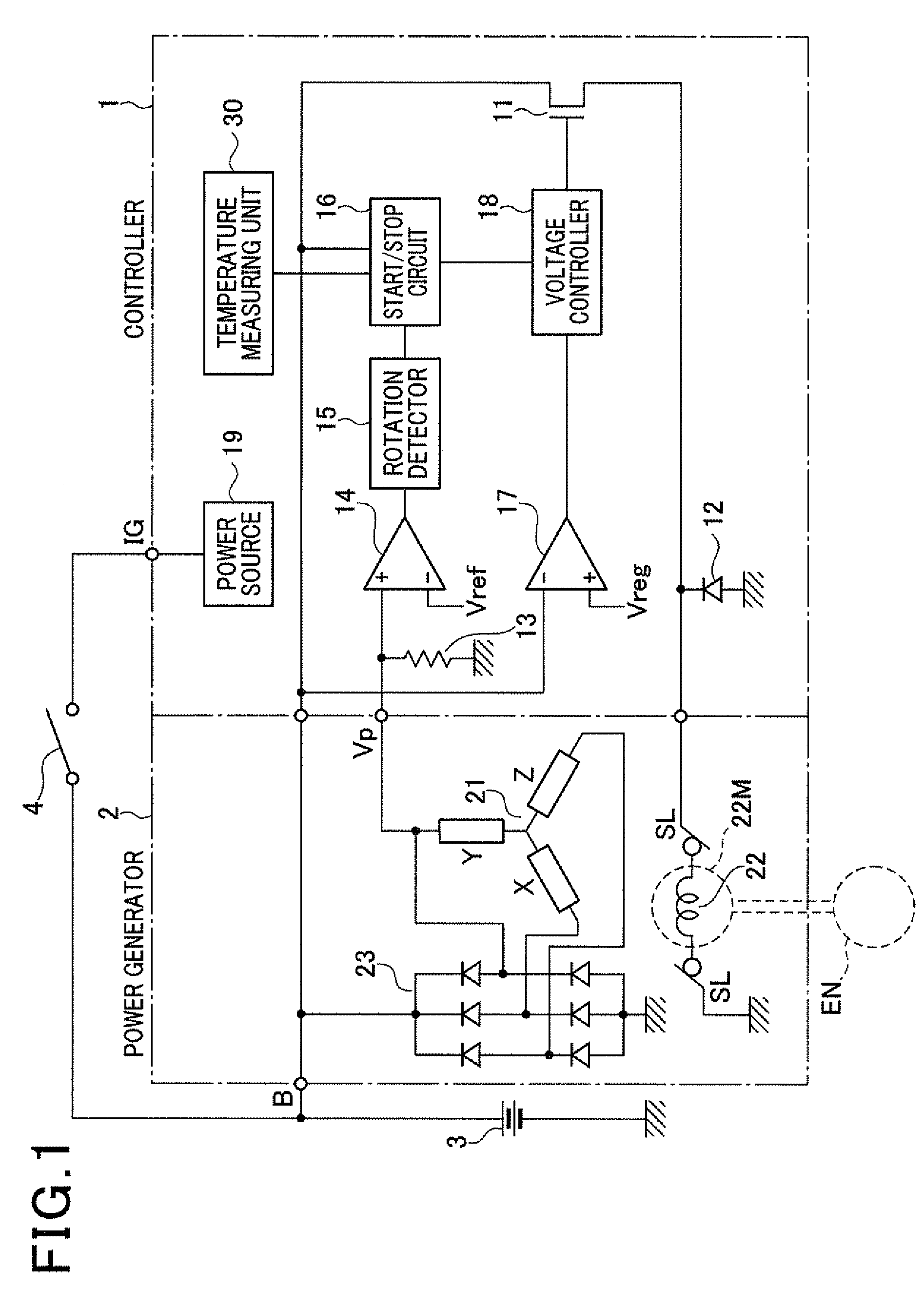
[0085]When the ignition switch 4 is turned on so that each component of the controller 1 is activated, a starting operation of the engine EN is carried out, and the voltage controller 18 operates in the initial excitation mode to control the MOSFET 11 to supply the initial value of the excitation current to the field winding 22 in step 400. In response to the start of the starting operation of the engine EN, the power-g...


PUM


Abstract

In a controller, a voltage controller operates, in an initial excitation mode, to turn selectively on and off a switch to supply an excitation current as an initial excitation current to the field winding, and operates, in a power generation mode, to selectively increase and reduce the excitation current to be supplied to the field winding to regulate an output voltage of the power generator to a target value. A mode-shift determiner determines, while the voltage controller operates in the initial excitation mode, whether to shift an operation mode of the voltage controller from the initial excitation mode to the power generation mode based on: a measured rotation number of a rotor, a threshold rotation number of the rotor, and a preset time period, the time period being equal to or longer than an expected maximum value of cycle of pulsations of rotation of the engine.

Description

CROSS REFERENCE TO RELATED APPLICATIONS[0001]This application is based on Japanese Patent Application 2010-275928 filed on Dec. 10, 2010. This application claims the benefit of priority from the Japanese Patent Application, so that the descriptions of which are all incorporated herein by reference.TECHNICAL FIELD[0002]The present disclosure relates to controllers for controlling power generators installed in motor vehicles; these generators are driven by rotational power supplied from an engine.BACKGROUND[0003]In a normal power generator installed in a motor vehicle, when a field winding of the power generator is intermittently energized by a voltage regulator while a rotor of the power generator is rotated by rotational power supplied from the internal combustion engine (engine) of the motor vehicle, the rotating field winding creates magnetic flux. The created magnetic flux magnetizes a plurality of field poles of the rotor. The rotation of the plurality of magnetized field poles ...

Claims


Application Information

Patent Timeline
Patent Type & Authority Patents(United States)
IPC IPC(8): H02H7/06
CPCH02P9/305H02P9/48H02P2009/002H02P2101/45
Inventor AKITA, KOUICHITASHIRO, TAKAHIKO
Owner DENSO CORP
Why Eureka
Try Eureka