Wind turbine for producing electrical power and a method of operating the same

a technology of wind turbines and wind power, which is applied in the direction of machines/engines, electric generator control, greenhouse gas reduction, etc., can solve the problem that the electrical power to be produced may not vary

Inactive Publication Date: 2007-03-13
GE POWER CONVERSION
View PDF17 Cites 22 Cited by
  • Summary
  • Abstract
  • Description
  • Claims
  • Application Information

AI Technical Summary

Problems solved by technology

However, on the other hand, the electrical power to be produced may not vary.

Method used


Image

  • Wind turbine for producing electrical power and a method of operating the same
  • Wind turbine for producing electrical power and a method of operating the same

Examples


Embodiment Construction

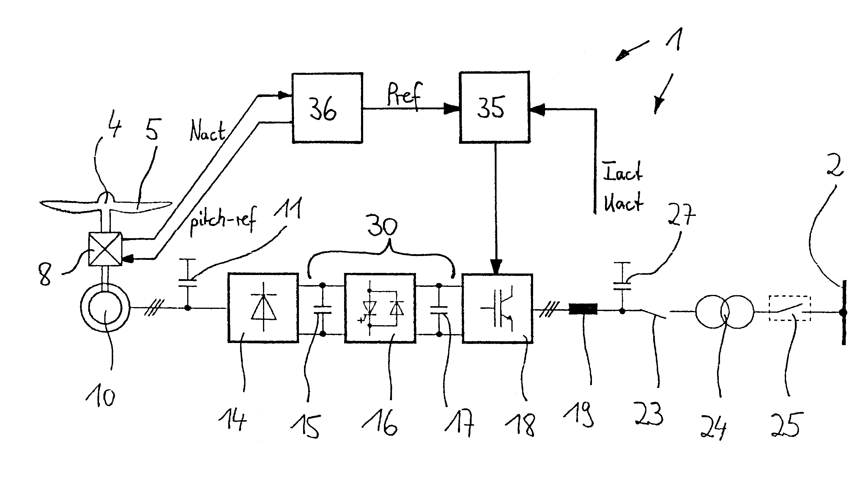
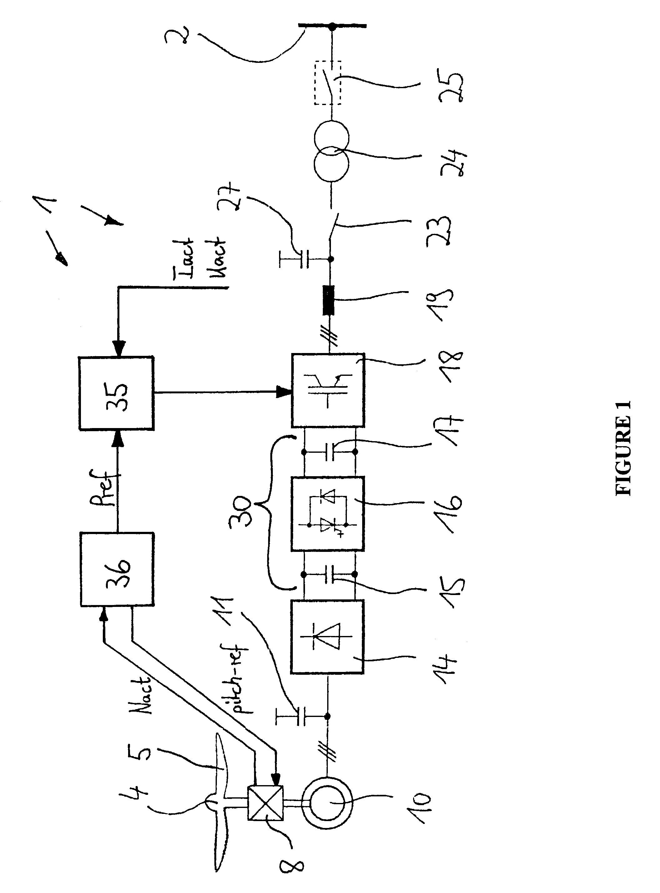
[0010]FIG. 1 illustrates a variable speed wind turbine 1 that supplies electrical power with a fixed frequency to a utility grid 2.

[0011]The wind turbine 1 includes a turbine rotor 4 with at least one rotor blade 5. The pitch of the blade 5 is variable and may be controlled. The turbine rotor 4 is mounted on a rotatable shaft. The turbine rotor 4 is mechanically coupled by the shaft to a gear box 8 which is mechanically coupled by a further rotatable shaft to the rotor of a three-phase synchronous generator 10.

[0012]The gear box 8 includes a step-up speed transmission with a fixed ratio so that the rotor of the generator 10 rotates at a fixed multiple speed of the turbine rotor 4.

[0013]The generator 10 produces a three-phase alternating output current with a variable frequency that is proportional to the speed of the turbine rotor 4. The output voltage of the generator 10 depends on its speed and its flux. In case of constant flux, the output voltage of the generator 10 is proportio...


PUM


Abstract

A wind turbine includes a turbine rotor with at least one blade and a generator with a rotor and a stator. The turbine rotor is mechanically coupled with the rotor of the generator. A diode rectifier is electrically coupled to the stator of the generator. A direct current link is electrically coupled with the diode rectifier. A line converter is electrically coupled with the direct current link.

Description

[0001]Pursuant to the provisions of 35 U.S.C. 119, this Application claims priority to European Application No. 03 290 876.6, filed Apr. 8, 2003 in the European Intellectual Property Office, the disclosure of which is incorporated herein in its entirety by reference.FIELD OF INVENTION[0002]The present invention generally relates to a wind turbine for producing electrical power and to a method of operating a wind turbine.BACKGROUND OF THE INVENTION[0003]Wind turbines for producing electrical power are generally known. In particular, wind turbines with variable speed are well known. On one hand, the speed of these wind turbines depends on the actual wind situation. However, on the other hand, the electrical power to be produced may not vary. Instead, the electrical power must be delivered with a fixed frequency e.g. to a utility grid.SUMMARY OF THE INVENTION[0004]An object of the present invention is to provide an improved wind turbine for producing electrical power.[0005]As well, it ...

Claims


Application Information

Patent Timeline
Patent Type & Authority Patents(United States)
IPC IPC(8): H02J3/36F03D7/02H02J3/38
CPCF03D7/0224F03D9/003H02J3/386F05B2220/70642Y02E10/723Y02E10/725Y02E10/763F05B2240/96F03D9/255F03D9/11F03D15/10H02J2300/28H02J3/381Y02E10/76Y02E10/72Y02E70/30
Inventor MOEHLENKAMP, GEORG
Owner GE POWER CONVERSION
Why Eureka
Try Eureka