Circuit structure for driving a plurality of cold cathode fluorescent lamps

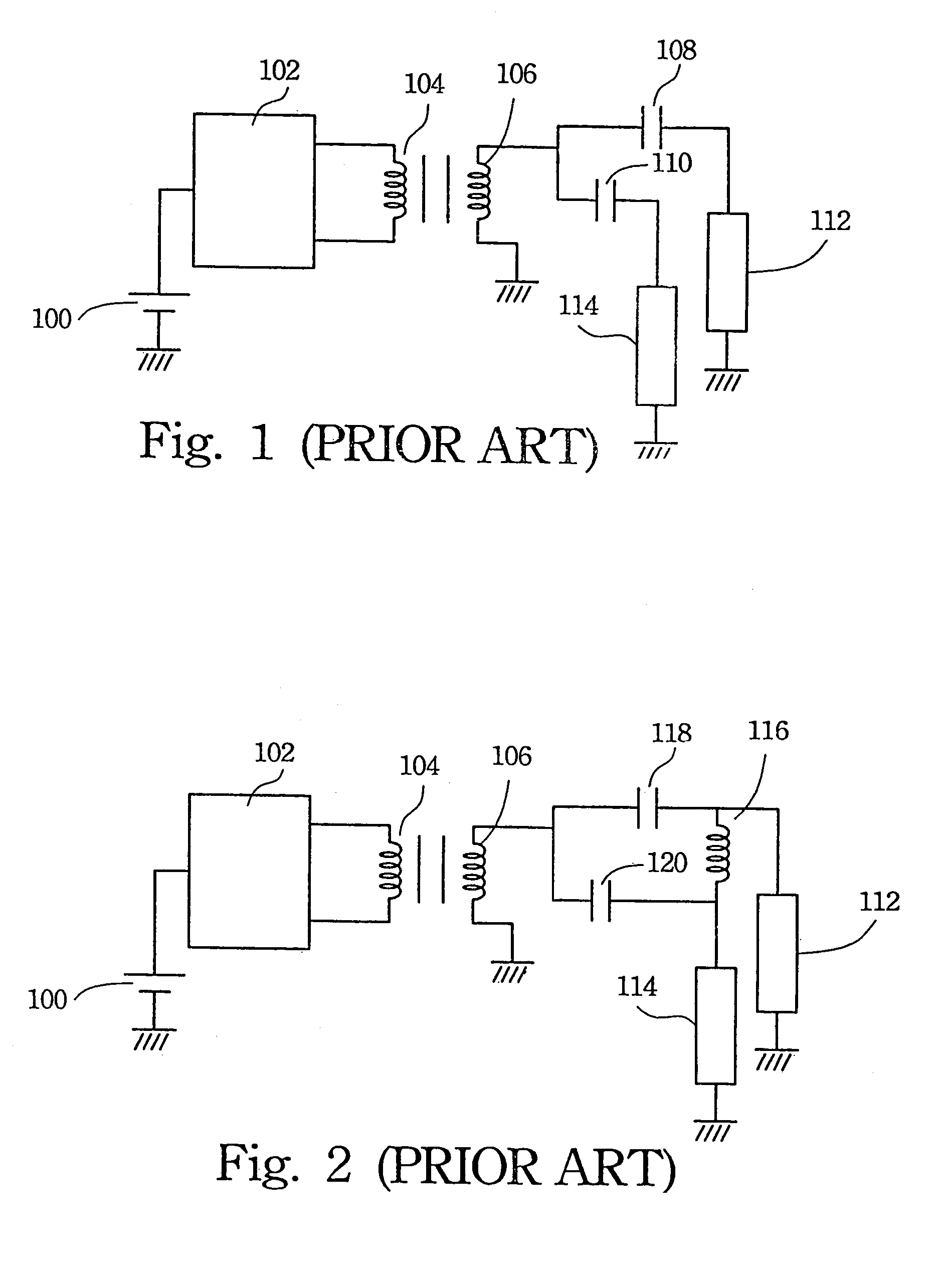
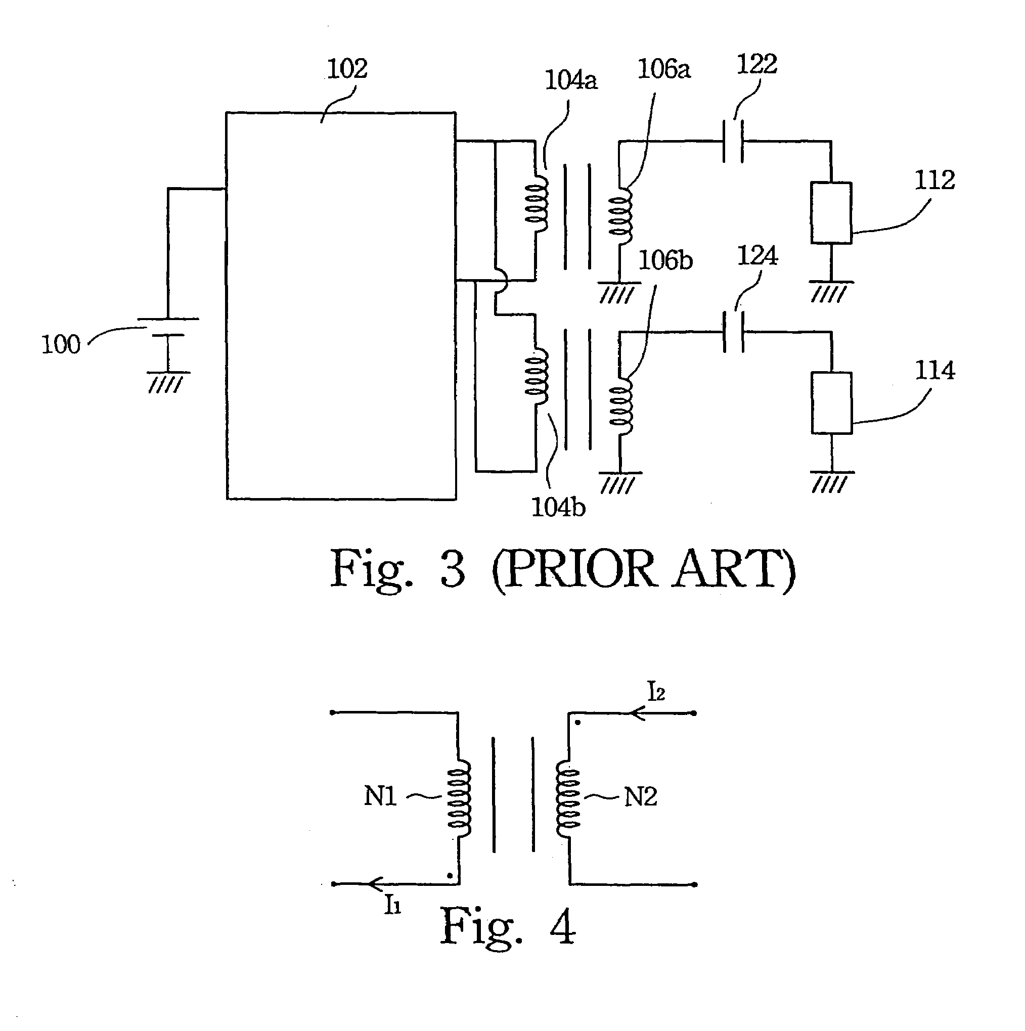
a technology circuit structures, which is applied in the direction of electric variable regulation, process and machine control, instruments, etc., can solve the problems of high cost and large size of the technique of using a plurality of dc/ac converters to drive a plurality of cold cathode fluorescent lamps as depicted in fig. 3

Inactive Publication Date: 2007-03-13
O2 MICRO INT LTD
View PDF6 Cites 67 Cited by
  • Summary
  • Abstract
  • Description
  • Claims
  • Application Information

AI Technical Summary

Benefits of technology

[0011]Another purpose of the present invention is to provide a DC / AC converter structure for driving a plurality of cold cathode fluorescent lamps that is not affected by operating frequency of a DC / AC power converter. Therefore, the circuit structure may balance the current flowing through each lamp.

Problems solved by technology

In accordance with the foregoing description, there are many drawbacks in the conventional DC / AC converters when driving a plurality of cold cathode fluorescent lamps.
For example, the first circuit structure depicted in the FIG. 1 cannot ensure that each lamp is ignited.
Moreover, it is difficult to balance the current flowing through each lamp.
Further, the technique of using a plurality of DC / AC converters to drive a plurality of cold cathode fluorescent lamps as depicted in the FIG. 3 is expensive and large in size.

Method used


Image

  • Circuit structure for driving a plurality of cold cathode fluorescent lamps
  • Circuit structure for driving a plurality of cold cathode fluorescent lamps
  • Circuit structure for driving a plurality of cold cathode fluorescent lamps

Examples


first embodiment

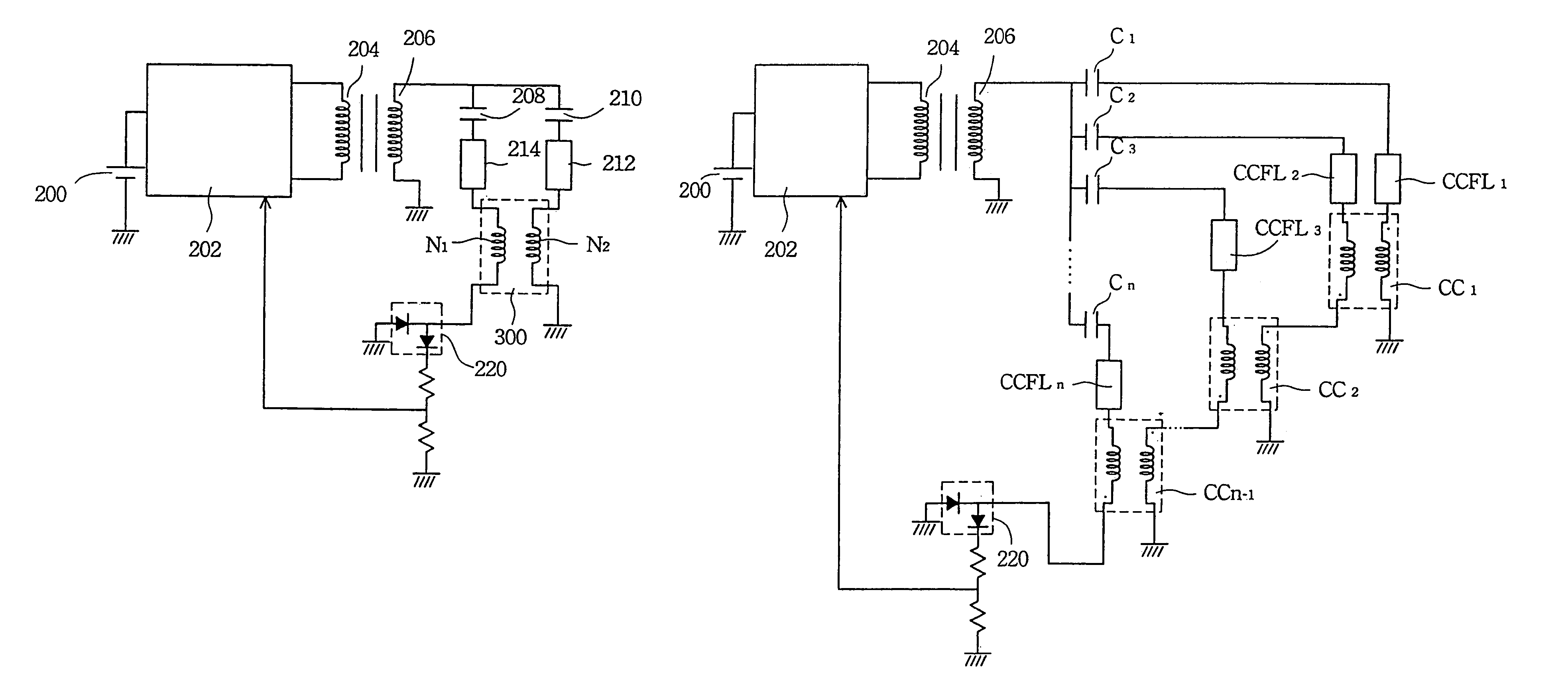
[0035]FIG. 5A is a schematic drawing of the common-mode choke 300 applied in a DC / AC converter to drive cold cathode fluorescent lamps in accordance with the present invention. A DC power 200 provides a DC power to the full bridge circuit 202. This DC power 200 is connected to a primary winding 204 of a transformer through the full bridge circuit 202. The secondary winding 206 of a transformer is coupled to two cold cathode fluorescent lamps 212 and 214 through two high voltage capacitors 208 and 210, respectively. The two cold cathode fluorescent lamps 212 and 214 are connected to the first winding N1 and the second winding N2 of the common-mode choke 300 of the present invention respectively. The cold cathode fluorescent lamp 214 is connected to the first winding N1 and the cold cathode fluorescent lamp 212 is connected to the second winding N2. The output of the common-mode choke 300 is connected to a dual diode 220 to feed back the current on the output of the full bridge circui...

second embodiment

[0036]FIG. 5B is a schematic drawing of the common-mode choke 300 applied to a DC / AC converter to drive two cold cathode fluorescent lamps in accordance with the present invention. A DC power 200 provides DC power to the full bridge circuit 202. DC power 200 is connected to a primary winding 204 of a transformer through the full bridge circuit 202. The secondary winding 206 of a transformer is coupled to the two input ends of the common-mode choke 300 of the present invention through two high voltage capacitors 208 and 210, respectively. The two output ends of the common-mode choke 300 are respectively connected to the two cold cathode fluorescent lamps 212 and 214. The cold cathode fluorescent lamp 214 is connected to the first winding N1 and the cold cathode fluorescent lamp 212 is connected to the second winding N2. The other end of the cold cathode fluorescent lamp 214 is connected to a dual diode 220 to feed back the current on the output end of the cold cathode fluorescent lam...

third embodiment

[0060]FIG. 9 is a drawing comparing the current flowing through the two cold cathode fluorescent lamps when the DC / AC converter is used to drive two cold cathode fluorescent lamps in accordance with the present invention. In accordance with the comparison drawing, the current flowing through the two cold cathode fluorescent lamps are almost equal. Obviously, the circuit structure of the present invention balances the current flowing through the two cold cathode fluorescent lamps respectively.

[0061]FIG. 10A is a schematic drawing of the DC / AC converter circuit structure of the third embodiment used to drive a plurality of cold cathode fluorescent lamps in accordance with the present invention. A DC power 200 provides a DC power to the full bridge circuit 202. This DC power 200 is connected to a primary winding 204 of a transformer through the full bridge circuit 202. The secondary winding 206 of a transformer is coupled to two high voltage capacitors 208 and 210. The high voltage cap...


PUM


Abstract

A DC / AC converter circuit structure for driving a plurality of cold cathode fluorescent lamps is described. A common-mode choke is used between the cold cathode fluorescent lamps. The common-mode choke balances the currents respectively flowing through the cold cathode fluorescent lamps.

Description

CROSS REFERENCE TO RELATED APPLICATIONS[0001]This application is a continuation of U.S. Nonprovisional application Ser. No. 10 / 383,277 filed Mar. 7, 2003 now U.S. Pat. No. 6,781,325, the teachings of which are herein incorporated by reference.FIELD OF THE INVENTION[0002]The present invention relates to a driver circuit, and more specifically, to a circuit for driving cold cathode fluorescent lamps.BACKGROUND OF THE INVENTION[0003]Both the notebook computers and the portable electronic apparatus use the cold cathode fluorescent lamp as a backlight because this lamp has the best illumination efficiency. Therefore, the cold cathode fluorescent lamp has quickly been adopted for use as the backlight in PDAs, notebook computers and portable electronic apparatus. The quality requirement of the converter for the cold cathode fluorescent lamp is also increased.[0004]A high voltage DC / AC converter is required to drive the cold cathode fluorescent lamp because this lamp uses a high AC operatio...

Claims


Application Information

Patent Timeline
Patent Type & Authority Patents(United States)
IPC IPC(8): H05B37/02H05B41/282
CPCH05B41/2822Y10S315/07
Inventor LEE, SHENG TAI
Owner O2 MICRO INT LTD
Why Eureka
Try Eureka