Stereo camera

a camera and stereo technology, applied in the field of stereo cameras, can solve the problems of troublesome manual operation of adjusting the angle of convergence, and the difficulty of obtaining a three-dimensional photograph

Inactive Publication Date: 2007-03-13
RICOH IMAGING COMPANY
View PDF20 Cites 124 Cited by
  • Summary
  • Abstract
  • Description
  • Claims
  • Application Information

AI Technical Summary

Benefits of technology

[0006]It is an object of the present invention to eliminate the drawbacks of the prior art mentioned above by providing a stereo camera which can take high-quality three-dimensional photographs by providing an ap

Problems solved by technology

Upon taking a picture using a stereo camera (stereoscopic camera) in which images of an object are recorded by at least a pair of photographing optical systems in a symmetrical arrangement in the lateral direction, if the object distance is relatively small or the photographing optical systems are made of tele

Method used


Image

  • Stereo camera
  • Stereo camera
  • Stereo camera

Examples


first embodiment

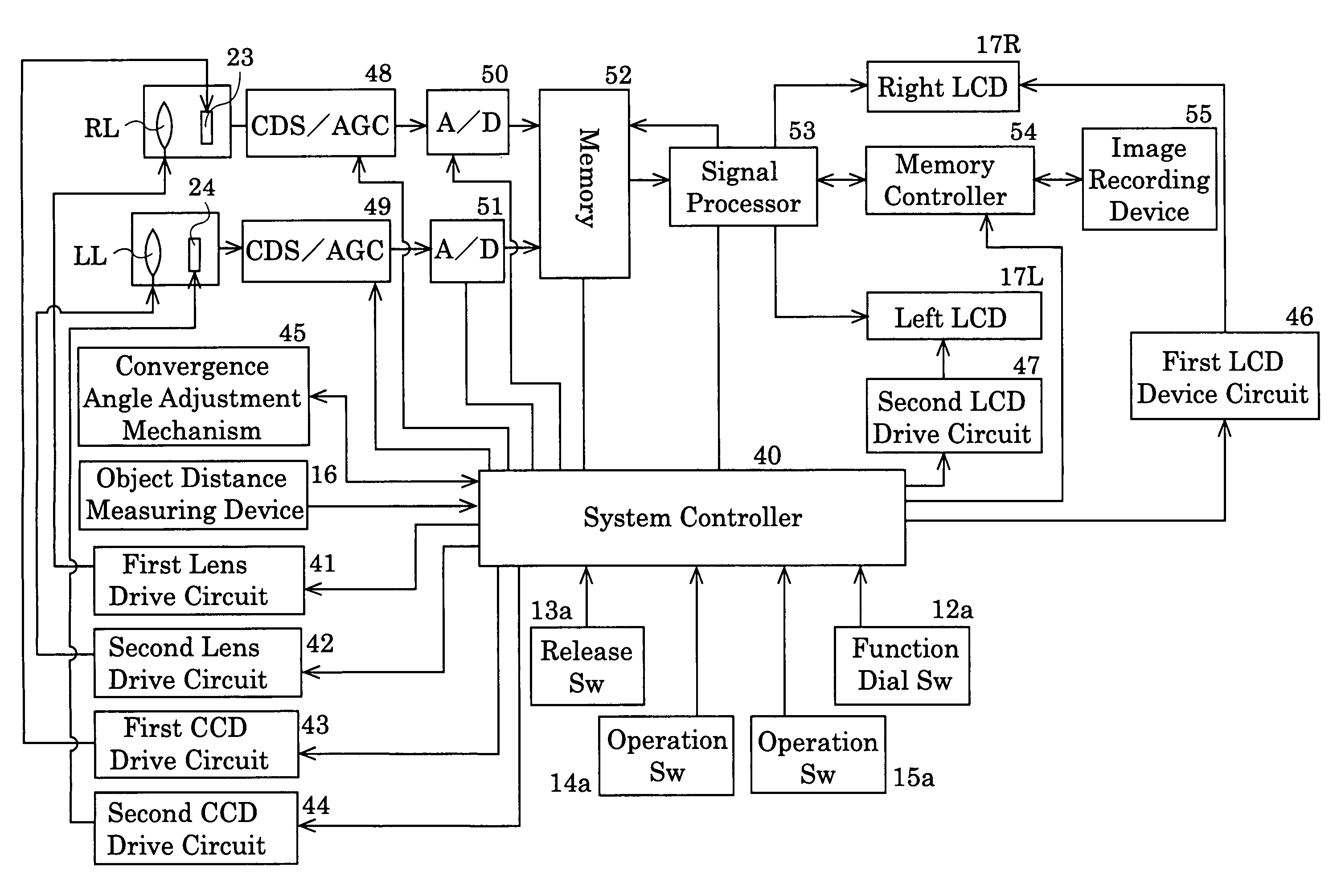
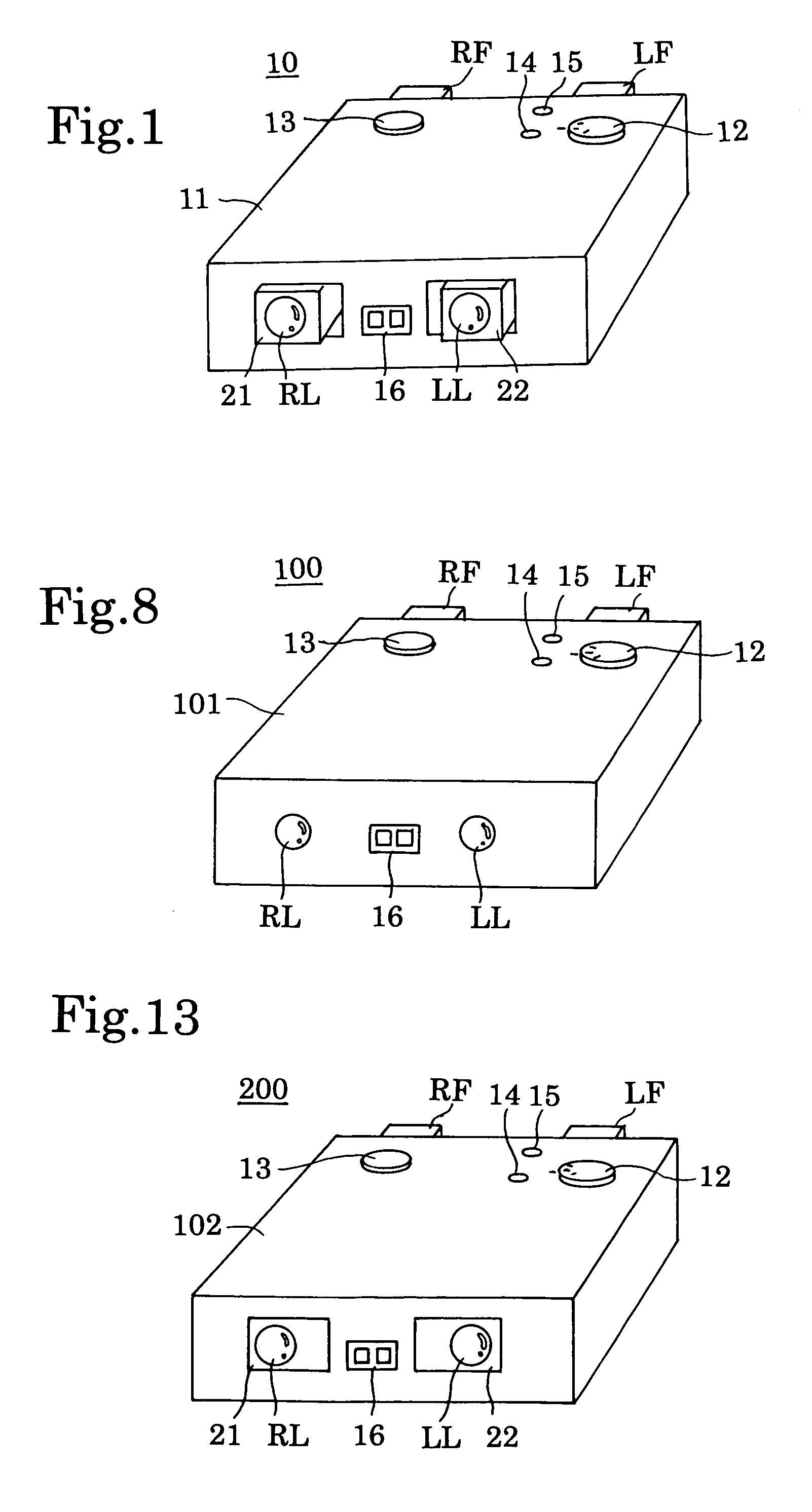
[0036]Embodiments of the present invention will be discussed below with reference to the drawings. FIG. 1 shows a stereo camera according to the present invention. The stereo camera 10 is an electronic still camera in which an object is photographed using an image pickup device and is comprised of a box-shaped housing 11 which is provided on the front portion thereof with a pair of right and left photographing optical systems RL and LL and on the rear portion thereof with a pair of right and left finder eyepiece portions RF and LF.

[0037]The housing 11 is provided on its upper surface with a function dial 12 which is adapted to turn the power source ON / OFF or select photographing modes, and a release button 13. A pair of operation buttons 14 and 15 are provided in the vicinity of the function dial 12 to select the frames or exposure correction value, etc. Also, an active type infrared object distance metering device 16 is provided on the front surface of the housing 11 and between th...

second embodiment

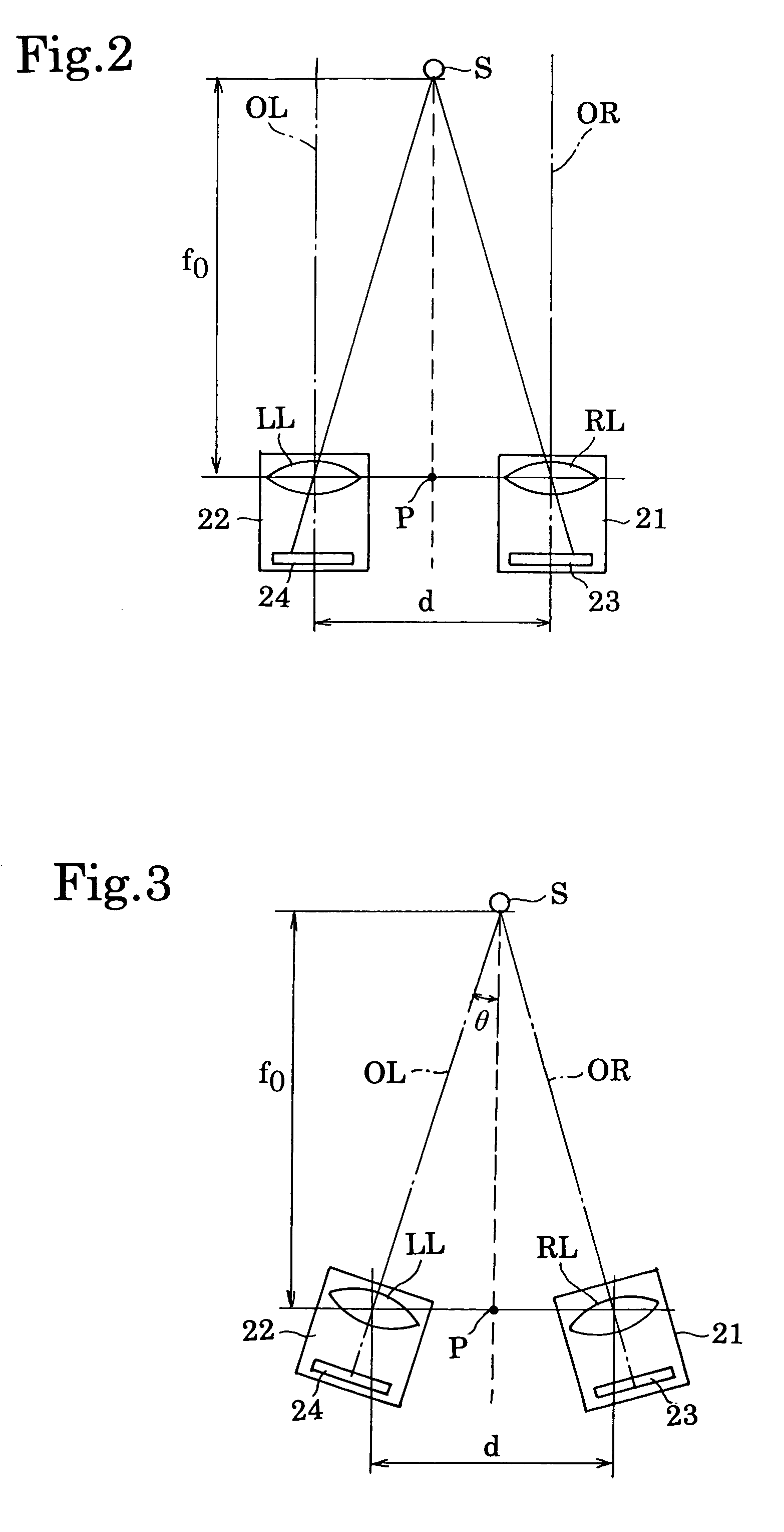
[0065]At step S118 in the second embodiment, the variable apex angle Φ is determined in accordance with the following expression (2):

Φ=(n−1)θ  (2)

[0066]wherein “Φ” represents the variable apex angle (°) “n” represents the refractive index of the variable angle prisms RV and LV, and “θ” represents half of the convergence angle (deflection angle) (°), respectively.

[0067]Table 2 below shows a relationship between the object distance fo and the variable apex angle Φ when the base length d is 65 mm and the refractive index n is 1.5, respectively, in the stereo camera 100 according to the second embodiment.

[0068]

TABLE 2fo (m)Φ (°)10.93120.46650.186100.093

[0069]FIG. 13 shows a third embodiment of a stereo camera according to the present invention. The stereo camera 200 is an electronic still camera similar to the stereo camera 10 in the first embodiment. The camera 200 includes a box-like housing 101 which is provided on the front surface thereof with a pair of right and left photographing...

third embodiment

[0075]At step S120 in the third embodiment, the amount of shift (displacement) is determined in accordance with the following expression (3);

y=f·tan ω  (3)

tan ω=0.5d / (fo+f)

[0076]wherein “y” represents the amount of shift (displacement) (mm), “f” represents the focal length of the lens (mm), “ω” represents half of the convergence angle (°), and “d” represents the base length between the right and left photographing optical systems RL and LL, respectively.

[0077]Although the variable angle prisms RV and LV are provided on the object sides of the right and left photographing optical systems RL and LL in the second embodiment, the arrangement of the variable angle prisms is not limited thereto. Namely, the variable angle prisms can be located at any positions within the light paths of the right and left photographing optical systems RL and LL. For instance, the same technical effect can be expected from an alternative arrangement in which the variable angle prisms RV and LV are provided...


PUM


Abstract

A stereo camera includes a pair of photographing optical systems arranged in a common plane so that a common photographing coverage occurs between a pair of photographing areas taken by the pair of photographing optical systems, an object distance measuring device, a convergence angle adjustment mechanism adapted to vary an angle of convergence defined by, and between, the optical axes of the pair of photographing optical systems, so as to adjust an amount of common photographic coverage of the pair of photographing optical systems, and a controller adapted to control the convergence angle adjustment mechanism in accordance with object distance data obtained by the object distance measuring device.

Description

BACKGROUND OF THE INVENTION[0001]1. Field of the Invention[0002]The present invention relates to a stereo camera which takes a three-dimensional picture (stereoscopic photograph) for use in an optical system which gives a sensation of image depth to a viewer, due to a parallax produced between the viewer's eyes and convergence of the viewer's eyes.[0003]2. Description of the Related Art[0004]Upon taking a picture using a stereo camera (stereoscopic camera) in which images of an object are recorded by at least a pair of photographing optical systems in a symmetrical arrangement in the lateral direction, if the object distance is relatively small or the photographing optical systems are made of telephotographic optical systems, the photographic coverage (overlap) of right and left field angles is made small, and hence it is difficult to obtain a three-dimensional photograph.[0005]A known solution thereto is to give an angle of convergence to the right and left photographing optical ax...

Claims


Application Information

Patent Timeline
IPC IPC(8): H04N13/00H04N5/225G02B7/28G03B5/02G03B13/36G03B15/00G03B19/02G03B19/07G03B35/08H04N13/02
CPCG03B35/08H04N13/0246H04N13/0239H04N13/239H04N13/246
Inventor ABE, TETSUYASENSUI, TAKAYUKI
Owner RICOH IMAGING COMPANY
Why Eureka
Try Eureka