Thin-film magnetic head having the length of the pinned and antiferromagnetic layers greater than the width dimension thereof and/or the length of the free layer

a thin-film magnetic head and antiferromagnetic layer technology, applied in special recording techniques, instruments, nanoinformatics, etc., can solve problems such as output deterioration and conventional thin-film magnetic heads with cpp structures, and achieve enhanced and stabilized hard disk drive output, restrain the direction of magnetization of the pinned layer, and suppress the effect of inclination in the direction of magnetization more effectively

Active Publication Date: 2007-03-13
TDK CORPARATION
View PDF8 Cites 12 Cited by
  • Summary
  • Abstract
  • Description
  • Claims
  • Application Information

AI Technical Summary

Benefits of technology

[0010]In the thin-film magnetic head of the present invention, the length of each of the pinned layer and antiferromagnetic layer in their contact area in a depth direction (MR height direction) from a surface facing a medium is longer than that of the free layer in the same direction. The magnetization of the pinned layer is fixed to the MR height direction, a direction opposite therefrom, or the like, for example. When the length of the pinned layer in the depth direction is set longer as such, the demagnetizing field in the MR height direction is reduced, so that the magnetization in the height direction or in the direction opposite there from is stabilized, whereby the direction of magnetization of the pinned layer can be restrained from being tilted by disturbances.
[0011]Also, the pinned layer and the antiferromagnetic layer have the same length in their contact area-in-the MR height direction, so that the pinned layer is in contact with the antiferromagnetic layer throughout its length in the MR height direction, thus raising the exchange coupling force, whereby the inclination in the direction of magnetization can be suppressed more effectively.
[0013]Since the head gimbal assembly and hard disk drive in accordance with the present invention comprise the above-mentioned thin-film magnetic head, they can restrain the direction of magnetization of the pinned layer from tilting, thereby being able to enhance and stabilize the output of the hard disk drive.
[0015]In such a thin-film magnetic head, the length of each of the pinned layer and antiferromagnetic layer in their contact area in the MR height direction is longer than that of the contact area in the width direction thereof. When the length of the pinned layer in the depth direction is set longer as such, the demagnetizing field in the MR height direction is reduced, so that the magnetization in the height direction or in the direction opposite therefrom is stabilized, whereby the direction of magnetization of the pinned layer can be restrained from being tilted by disturbances.
[0016]Also, the pinned layer and the antiferromagnetic layer have the same length in their contact area in the MR height direction, so that the pinned layer is in contact with the antiferromagnetic layer throughout its length in the MR height direction, thus raising the exchange coupling force, whereby the inclination in the direction of magnetization can be suppressed more effectively.
[0017]The head gimbal assembly and hard disk drive comprising such a thin-film magnetic head can restrain the direction of magnetization of the pinned layer from tilting, thereby being able to enhance and stabilize the output of the hard disk drive.

Problems solved by technology

However, conventional thin-film magnetic heads with the CPP structure may have the following problems.
As the device size becomes smaller, the pinned layer of CoFe or the like whose direction of magnetization is fixed by an antiferromagnetic layer of PtMn or the like is more likely to tilt the direction of magnetization and generate pin inversions, because of annealing in a later step, external magnetic fields, and magnetic fields caused by the sense current, thereby yielding problems of output deterioration and the like.

Method used


Image

  • Thin-film magnetic head having the length of the pinned and antiferromagnetic layers greater than the width dimension thereof and/or the length of the free layer
  • Thin-film magnetic head having the length of the pinned and antiferromagnetic layers greater than the width dimension thereof and/or the length of the free layer
  • Thin-film magnetic head having the length of the pinned and antiferromagnetic layers greater than the width dimension thereof and/or the length of the free layer

Examples


example

[0053]Effects of the present invention will now be explained specifically with reference to an example.

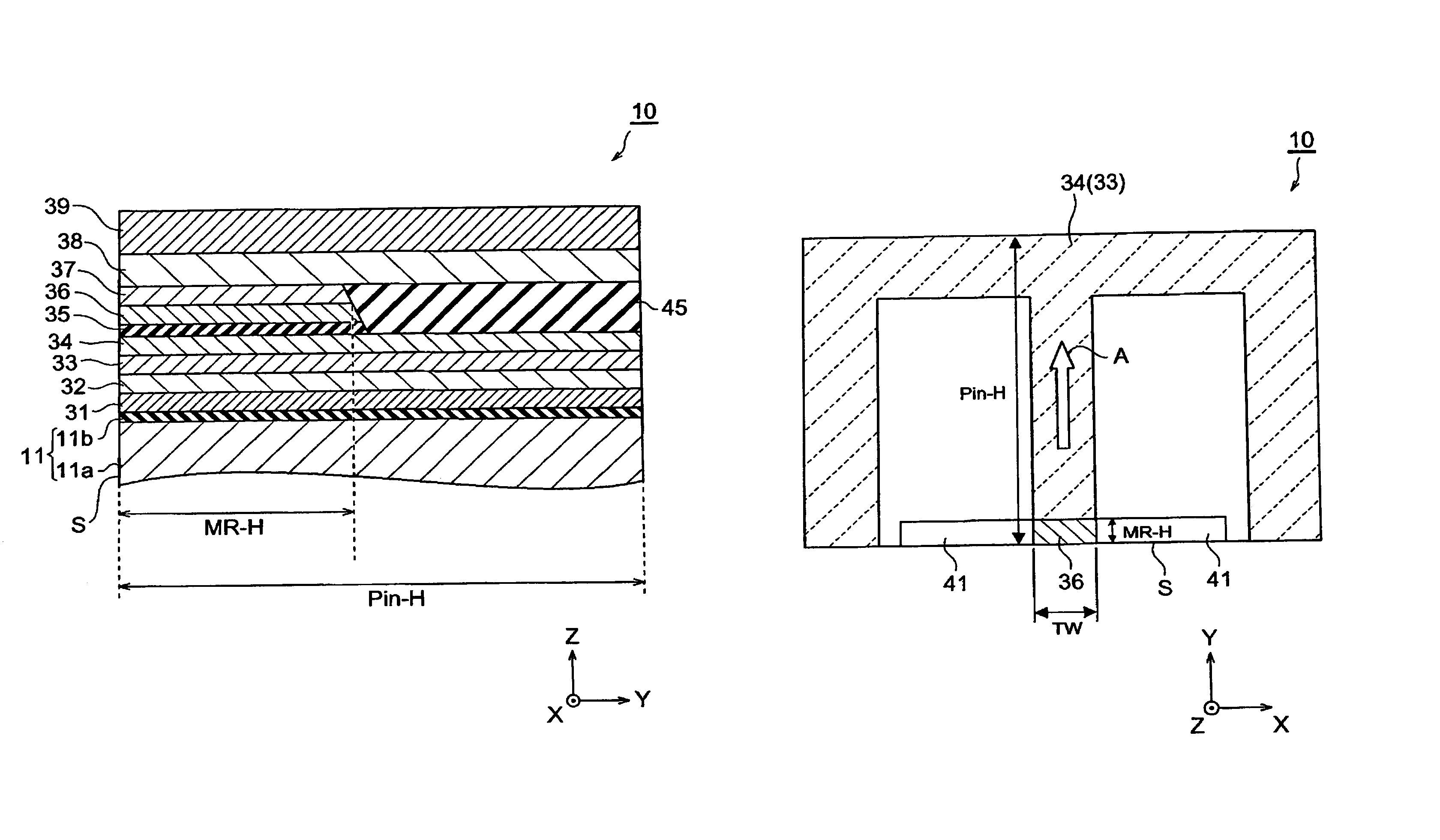
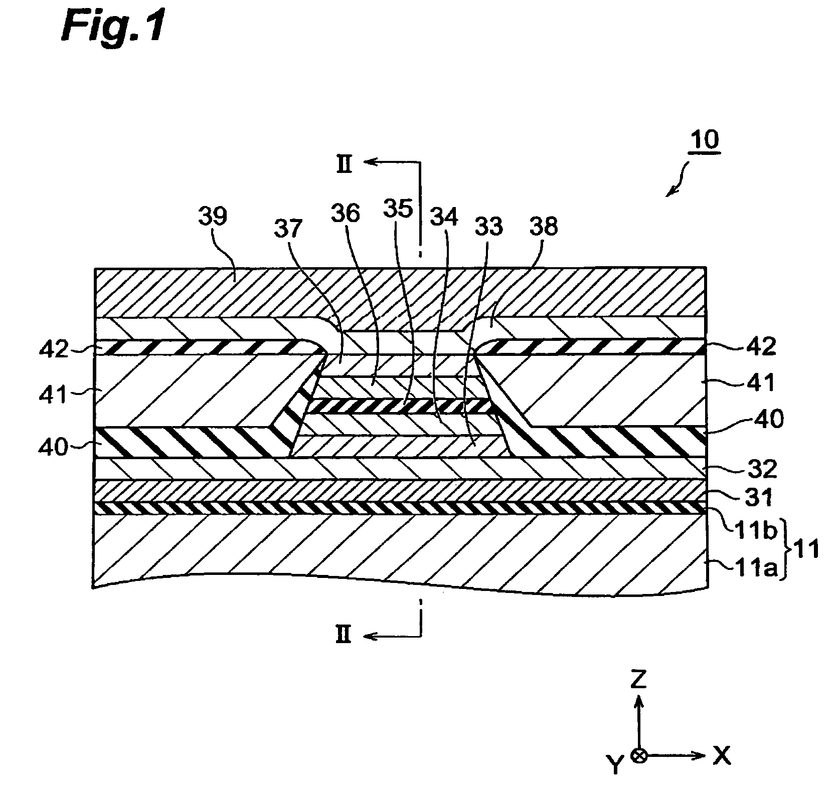
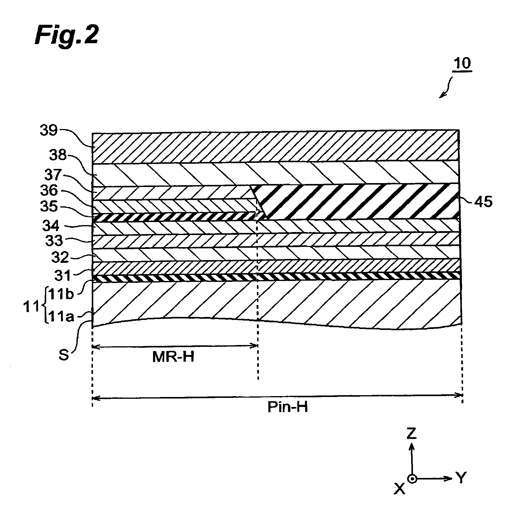
[0054]First, as the example, the thin-film magnetic head (TMR) having the configuration shown in Table 1 was prepared. The numerals shown in this table correspond to those in FIGS. 1 and 2. When a layer has a multilayer structure, the sublayers therein are listed while being separated from each other by slashes, so that they are shown in ascending order from the left side.

[0055]In this example, in the contact area between the pinned layer (CoFe / Ru / CoFe) and the pinning layer (PtMn), the height (Pin-H) of each layer in the MR height direction was made longer than the length (MR-H) of the free layer (CoFe / NiFe) 36 in the same direction. Also, in the contact area between the pinned layer (CoFe / Ru / CoFe) and the pinning layer (PtMn), these layers were made to have the same length in the MR height direction.

[0056]

TABLE 1NUMERALLAYER NAMEFORMING MATERIAL39UPPER SHIELDNiFe (2 μm)LAYER382ND...


PUM

PropertyMeasurementUnit
MR heightaaaaaaaaaa
thicknessaaaaaaaaaa
thicknessaaaaaaaaaa

Abstract

In the thin-film magnetic head of the present invention, the length of each of a pinned layer and an antiferromagnetic layer in their contact area in the depth direction from a surface facing a medium is longer than the length of a free layer in the same direction. When the length of the pinned layer in the depth direction is set longer as such, the direction of magnetization of the pinned layer can be restrained from being tilted by disturbances. Also, the pinned layer and the antiferromagnetic layer have the same length in their contact area in the MR height direction, so that the pinned layer is in contact with the antiferromagnetic layer throughout its length in the MR height direction, thus raising the exchange coupling force, whereby the inclination in the direction of magnetization can be suppressed more effectively.

Description

BACKGROUND OF THE INVENTION[0001]1. Field of the Invention[0002]The present invention relates to a thin-film magnetic head, a head gimbal assembly, and a hard disk drive which read magnetic information of a hard disk or the like by utilizing a magnetoresistive effect.[0003]2. Related Background Art[0004]As a thin-film magnetic head for reading magnetic information of a hard disk, MR (MagenetoResistive) heads have been in use. The MR heads utilize a magnetoresistive effect in which the ohmic value of a magnetic body varies as an external magnetic field (e.g., a leakage magnetic field from the hard disk) changes when a current is caused to flow through the magnetic body. This magnetoresistive effect can substantially be realized by an MR film comprising a pinned layer whose direction of magnetization is fixed by exchange coupling with an antiferromagnetic layer, a free layer whose direction of magnetization varies depending on the external magnetic field, an intermediate layer dispose...

Claims


Application Information

Patent Timeline
Patent Type & Authority Patents(United States)
IPC IPC(8): G11B5/39G11B5/00G11B5/012G11B5/31G11B5/48
CPCB82Y10/00B82Y25/00G11B5/3909G11B5/3903G11B5/012G11B5/3116G11B5/3163G11B2005/3996G11B5/3932G11B5/4806G11B2005/0008G11B2005/0016
Inventor KAGAMI, TAKEOKASAHARA, NORIAKI
Owner TDK CORPARATION
Why Eureka
Try Eureka