Fiber and wire communication system

a communication system and fiber-wire technology, applied in the field of communication systems, can solve problems such as stress on current systems to their limits, and achieve the effects of reducing communication traffic between the mux-node and the head-end, simplifying routing tasks, and increasing efficiency

Inactive Publication Date: 2007-03-13
AMERICAN TELEPHONE & TELEGRAPH CO
View PDF17 Cites 36 Cited by
  • Summary
  • Abstract
  • Description
  • Claims
  • Application Information

AI Technical Summary

Benefits of technology

[0006]This invention provides a new architecture for a communication system between head-ends and end-users that expands capacity, simplifies transmission and operation, increases reliability and reduces cost of the communication system. One or more mux-nodes in the new architecture receive communication signals from a head-end and forward the received communication signals to one or more mini-fiber nodes (mFNs). The mFNs provide full duplex communication to the end-users. The head-end may include primary hubs that provide connectivity among all end-users of the communication system. The primary hubs also serve as information sources providing services such as TV broadcast signals. The head-end may also include secondary hubs that perform functions such as optical signal distribution and system recovery.
[0007]The head-end may be connected to one or more mux-nodes where each of the mux-nodes are connected to the head-end via a small number of optical fibers (preferably two or four). A mux-node may be connected to one or more mFNs via one or more optical fibers, and each of the mFNs may be connected to one or more end-users via passive wired connections such as coaxial lines. In this way, the number of connections to the head-end may be much smaller than if mFNs are connected directly to the head-end without the mux-node.
[0012]The mux-node may receive communication signals from end-users through the mFNs that are destined to other end-users connected to the mFNs being served by the same mux-node. In this situation, the mux-node may route the communication signals among mFNs without forwarding the information to the head-end. In addition, routing functions may be performed in the mFNs also. For example, the mFNs may detect that a communication is destined to one of the end-users also connected to the same mFN and route the communication to the end-user without processing by the respective mux-node. The mFNs may also assist the routing process by labeling or adding information to upstream communications so that routing tasks may be simplified at the mux-node, for example. In this way, communication traffic between the mux-node and the head-end may be reduced with corresponding increase in efficiency.
[0013]Reliability is increased because the mux-node reduces the number of optical fibers required to be connected to the head-end. The reliability is further increased because a greater distance is spanned by a smaller number of optical fibers between the head-end and the mux-node than distances spanned by a larger number of optical fibers between the mux-node and the mFNs. The wired connections to the end-users are passive and do not include active devices such as amplifiers and thus reduce power consumption and lengthen mean-time-to-failure (MTTF). The small number of optical fibers to the head-end and the lower power consumption of the wired connections shorten the mean-time-to-repair (MTTR) and reduce cost of the communication system.

Problems solved by technology

With increasing need for greater capacity, current systems are stressed to their limits.

Method used


Image

  • Fiber and wire communication system
  • Fiber and wire communication system
  • Fiber and wire communication system

Examples


Embodiment Construction

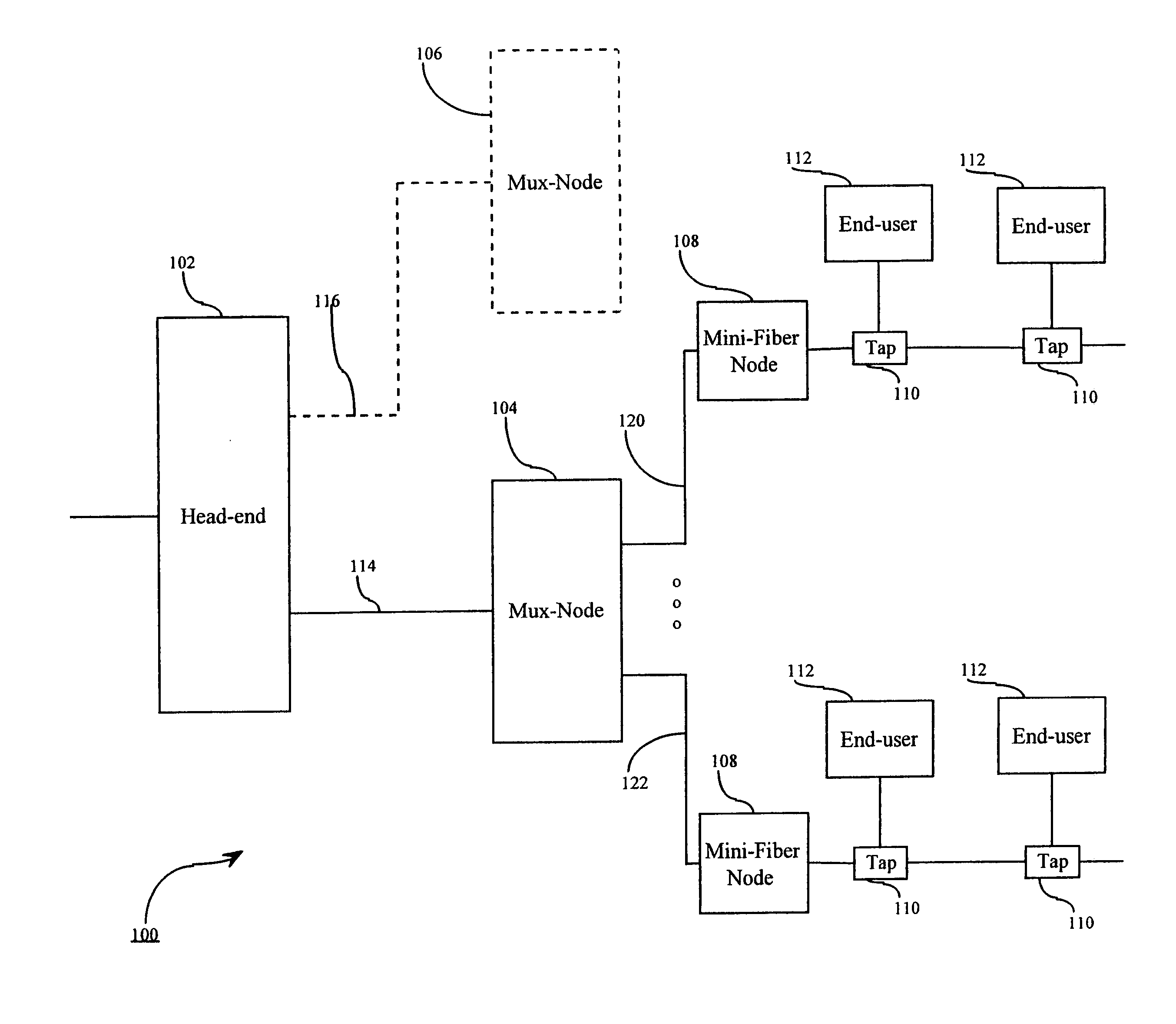
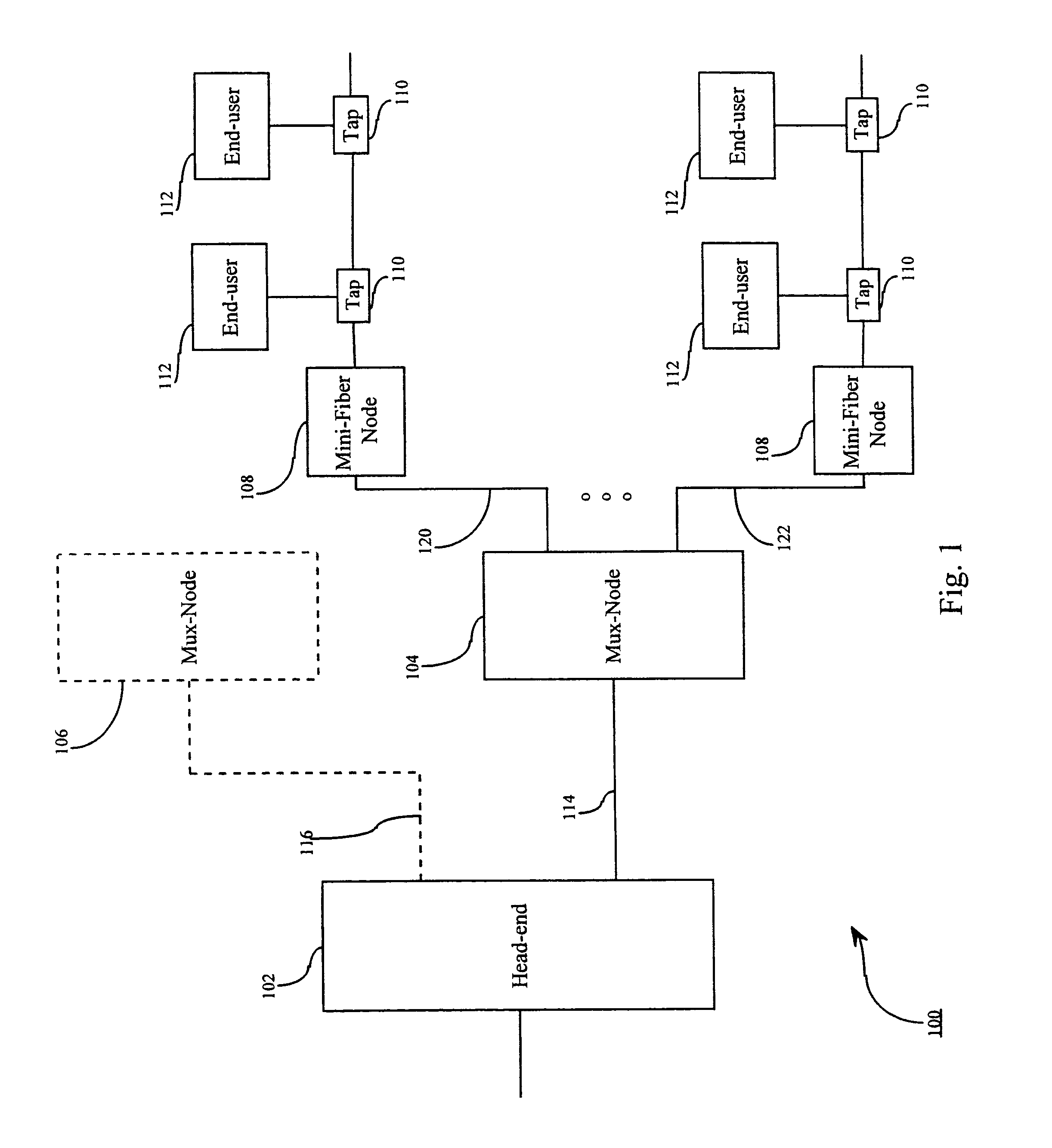
[0024]FIG. 1 shows an exemplary block diagram of a communication system 100 that includes a head-end 102, mux-nodes 104–106, mini-fiber nodes (mFNs) 108 and end-users 112. The mux-nodes 104–106 are connected to the head-end 102 via one or more optical fiber trunks 114–116, the mFNs 108 are connected to the mux-node 104 via optical fiber trunks 120–122 and the end-users 112 are connected to the mFNs 108 via passive wired connections such as coaxial lines via taps 110. Each of the optical fiber trunks 114–116 and 120–122 may include one or more optical fibers.

[0025]The head-end 102 may include primary hubs and secondary hubs (not shown) that form interconnected regional service facilities. The primary hubs may include a source of broadcast information such as TV broadcast signals and may have overall control of the communication system 100. Communication among the end-users 112 serviced by different mux-nodes 104–106 may be provided via the primary hubs because end-users 112 are reach...


PUM


Abstract

This invention provides a new architecture for a communication system between head-ends and end-users which expands bandwidth and reliability of the communication system. A mux-node receives communication signals from a head-end and forwards the received communication signals to one or more mini-fiber nodes. The connection to the head-end is via a small number of optical fibers and the connections to each of the mini-fiber nodes may be via one or more optical fibers that may provide full duplex communication. The head-end may communicate with the mux-node using digital or digital and analog signals. The mini-fiber nodes may combine the signals received from the head-end with loop-back signals used for local media access control prior to forwarding the signals to the end-users. Upstream data are received by the mini-fiber nodes and transmitted to the mux-node. The mux-node may route upstream communication signals received from the mini-fiber nodes as downstream signals to other mini-fiber nodes also connected to the mux-node without head-end interaction.

Description

[0001]This application is a continuation of U.S. non-provisional patent application no. 09 / 502,043, filed Feb. 11, 2000, now U.S. Pat. No. 6,751,417 entitled “Fiber and Wire Communication System,” which is a continuation-in-part of U.S. non-provisional patent application Ser. No. 09 / 460,770, filed Dec. 14, 1999, now U.S. Pat. No. 6,654,563 entitled “Fiber / Wired Communication System.” This application also claims the benefit of priority to provisional application No. 60 / 131,421, filed Apr. 28, 1999, entitled “HFC Architecture in the Making,” and provisional application No. 60 / 120,373, filed Feb. 17, 1999, entitled “Fiber / Wired Communication System.” The prior applications noted above are each incorporated herein by reference in its entirety.BACKGROUND OF THE INVENTION[0002]1. Field of Invention[0003]This invention relates to a communication system that includes fiber optic and wired media.[0004]2. Description of Related Art[0005]Cable communication systems use optical fibers to trans...

Claims


Application Information

Patent Timeline
Patent Type & Authority Patents(United States)
IPC IPC(8): H04J14/00H04B10/12H04N7/173H04N7/22
CPCH04B10/25751H04J14/0226H04J14/0282H04J14/0232H04N7/17309H04N7/22H04J14/0247H04J14/0252H04J14/0298H04J14/0227
Inventor COMBS, CHARLES D.DARCIE, THOMAS EDWARDDESAI, BHAVESH N.GNAUCK, ALAN H.LU, XIAOLINSANDINO, ESTEBANSNIEZKO, OLEH J.WERNER, ANTHONY G.WOODWARD, SHERYL LEIGH
Owner AMERICAN TELEPHONE & TELEGRAPH CO
Why Eureka
Try Eureka