Apparatus and method for controlling a programmable marking scribe

a scribe and scribe technology, applied in the field of marking scribes, can solve the problems of affecting identification accuracy and speed, additional manual effort when the marks are read, and the forms of marking often require manual effort when applied to marks

Active Publication Date: 2007-03-20
COLUMBIA MARKING TOOLS
View PDF40 Cites 24 Cited by
  • Summary
  • Abstract
  • Description
  • Claims
  • Application Information

AI Technical Summary

Problems solved by technology

These forms of marking often required manual effort when marks were applied and additional manual effort when the marks were read.
The previous and present systems solved many part identification problems and provided improved efficiencies, however a number of problems remain.
For example, surface roughness and data character deterioration, debilitation and obscuration still affect identification accuracy and speed.
Such problems usually worsen with time and wear, and demands for part tracking capabilities that extend beyond the manufacturing, storing and shipping of parts to the end of their useful lives have motivated the development of a two-dimensional marking process.
Disadvantages of electrochemical marking systems are that its automation can be difficult and that only conductive material can be processed.
Disadvantages of laser marking systems are that the equipment is relatively expensive and that the process is not readily applicable to irregular surfaces.
The parts, however, must be securely fixtured; and the noise level attending the process is relatively high.

Method used


Image

  • Apparatus and method for controlling a programmable marking scribe
  • Apparatus and method for controlling a programmable marking scribe
  • Apparatus and method for controlling a programmable marking scribe

Examples


Embodiment Construction

)

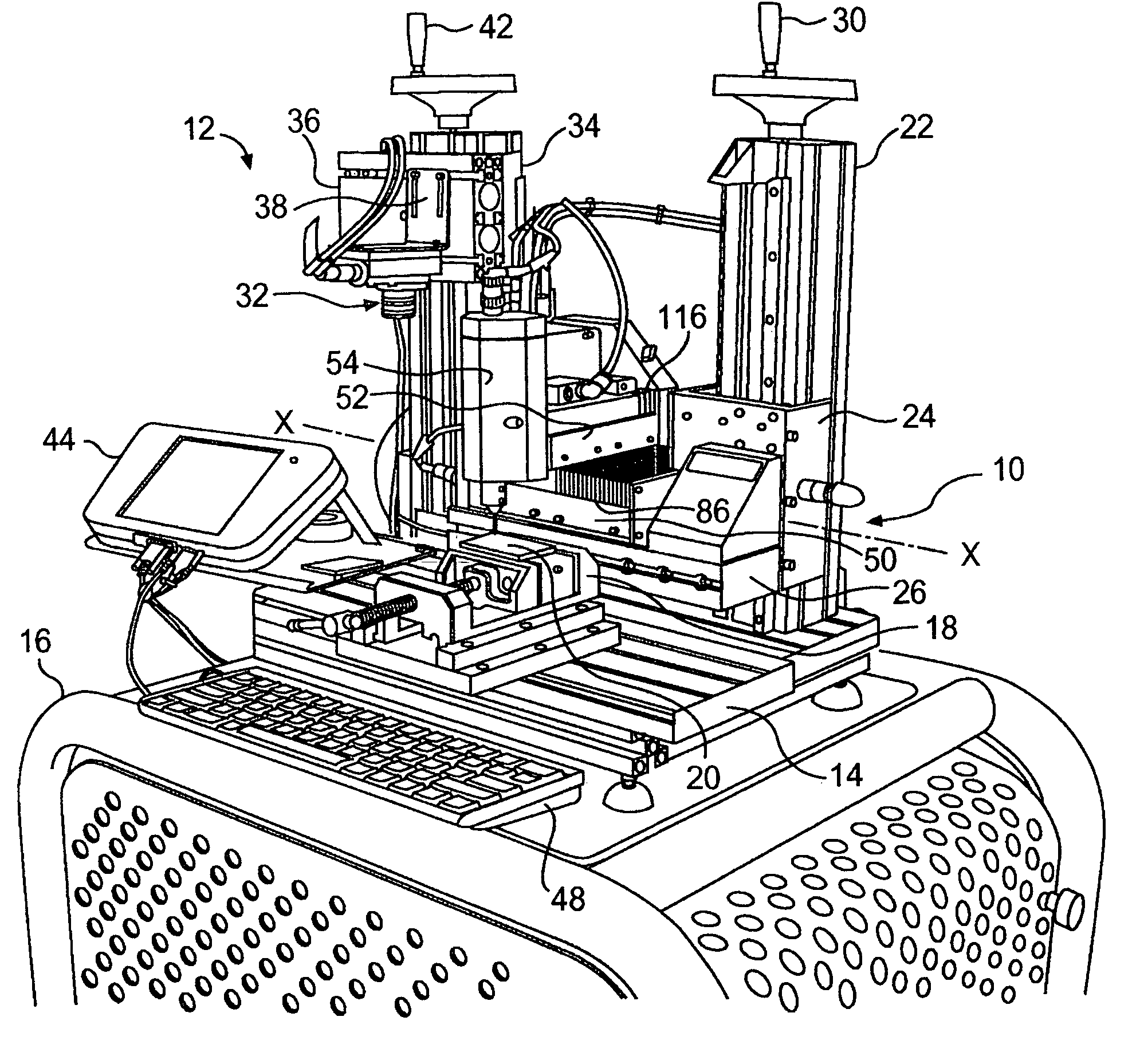
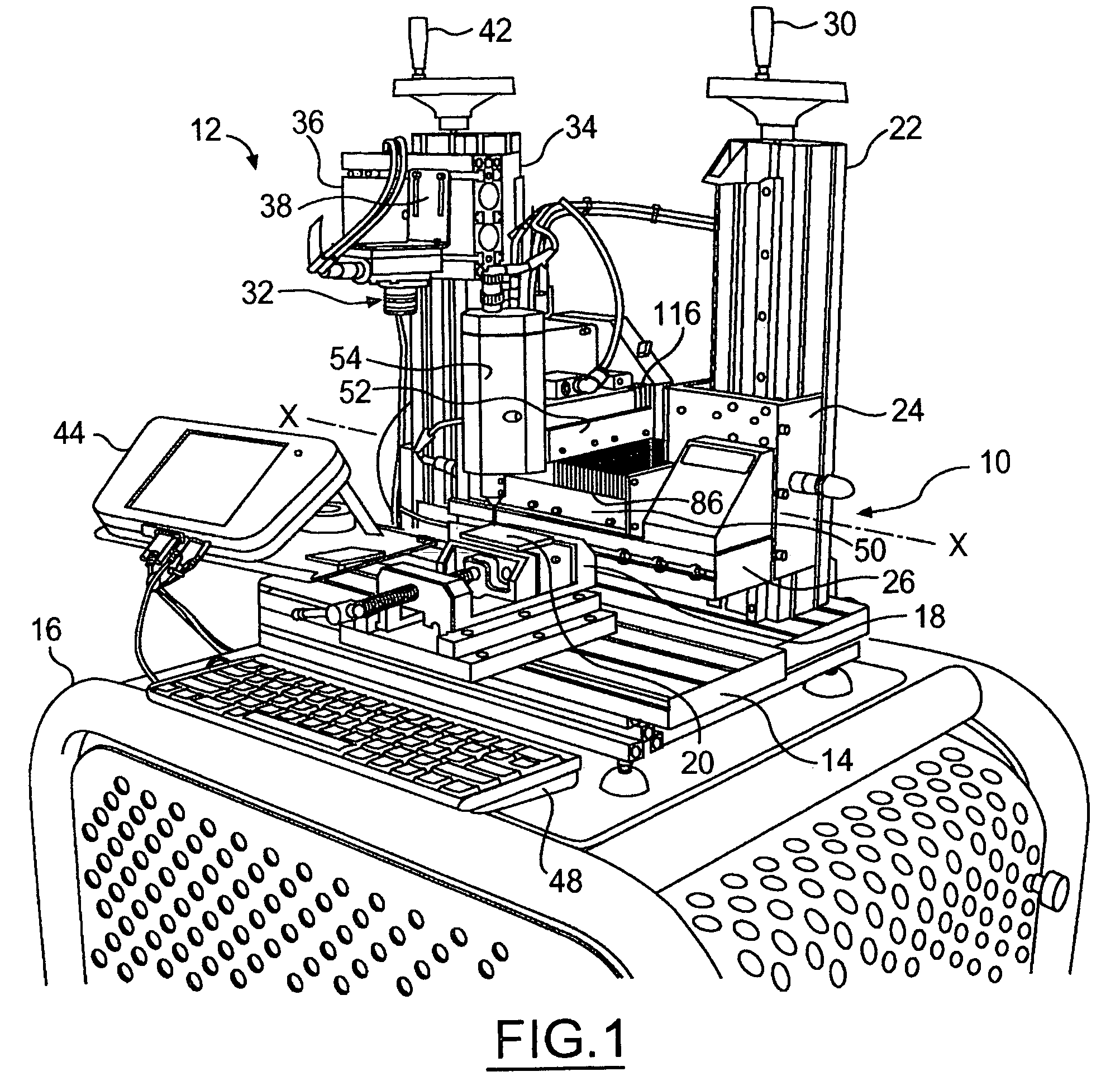
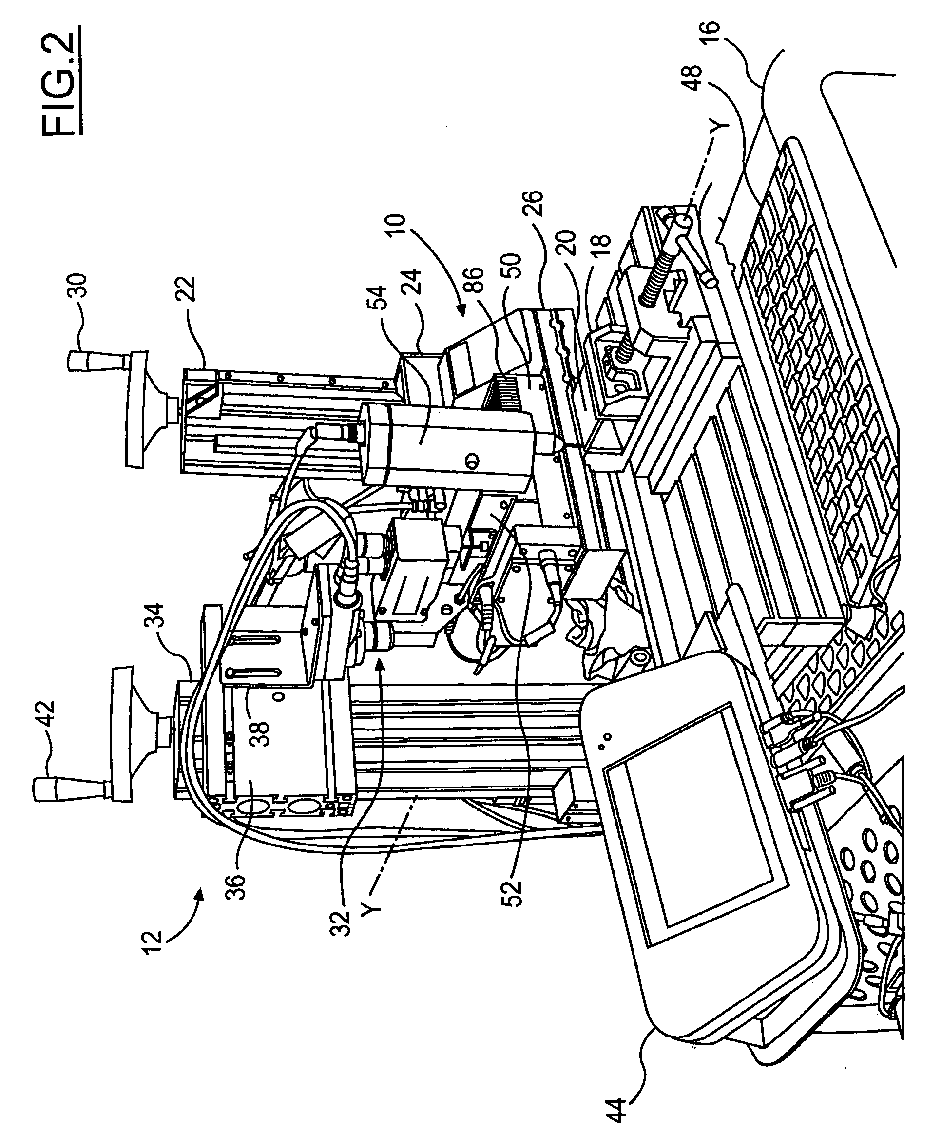
[0024]FIGS. 1, 2 and 3 show perspective views of the programmable marking scribe of the present invention. The marking scribe is generally indicated by the reference numeral 10 and is shown mounted on an apparatus exemplifying a marking station, generally indicated by the reference numeral 12. The marking station 12 includes a support base 14 mounted atop a stand 16. A workpiece holder 18 is mounted on the support base 14. The workpiece holder 18 is shown holding a representative workpiece, or part, 20; but it could be an object having a different size. A marking scribe support member 22 is shown extending upwardly from the support base 14, and a marking scribe slide 24 is shown slidably attached to the marking scribe support member 22. The marking scribe 10 is mounted on a marking scribe base 26, which is secured to the marking scribe slide 24. The marking scribe support member 22 has a marking scribe elevating screw 28 (best shown by FIG. 3) that is rotatable by a marking scribe ...


PUM


Abstract

A programmable marking scribe having a material displacement stylus movable in three mutually orthogonal axes to displace material from an object being marked and create a two-dimensional matrix of recessed areas formed of grooves and surrounded by ridges, the grooves and ridges forming a reflectively multifaceted data cell having a collective reflectance that is in contrast with unmarked surface reflectance to enable a reader to clearly distinguish the former from the latter even in the presence of extraneous interfering marks and deposits.

Description

BACKGROUND OF THE INVENTION[0001]1. Field of the Invention[0002]The present invention relates generally to marking scribes that encode data onto hard materials and more particularly to marking scribes that encode data represented by two-dimensional matrices.[0003]2. Background Art[0004]Marking systems used in applications such as part identification, tracking, inventory control, and order fulfillment are well known in the art. Early systems used characters attached to parts with tags, imprinted on parts with ink or paint, or punched into part surfaces. These forms of marking often required manual effort when marks were applied and additional manual effort when the marks were read. Later innovations including magnetic and optical alphanumeric data character recognition systems provided a degree of automated identification. A familiar and more recent system uses bar code recognition.[0005]The previous and present systems solved many part identification problems and provided improved e...

Claims


Application Information

Patent Timeline
Patent Type & Authority Patents(United States)
IPC IPC(8): B43L13/00B44B5/00
CPCB44B3/009B44B3/02B44F1/02B44C5/04B44C1/22
Inventor PHIPPS, THOMAS J.HABEDANK, ANDREW J.
Owner COLUMBIA MARKING TOOLS
Why Eureka
Try Eureka