Inflator

Inactive Publication Date: 2007-03-20
TOYOTA JIDOSHA KK
View PDF40 Cites 6 Cited by
  • Summary
  • Abstract
  • Description
  • Claims
  • Application Information

AI Technical Summary

Benefits of technology

[0017]The gas feed portions may be adapted to be activated at different timings. In this arrangement, by differentiating timings for activating the gas feed portions from one another, gas output characteristics of the gas feed portions can be obtained in a superimposed manner with a time difference. Thus, timings for activating the gas feed portions are adjusted and controlled, whereby a desired gas output characteristic can be achieved through simple adjustment and control of the gas characteristic of the inflator.
[0018]Each of the gas feed passages may communicate with at least one of front-seat and rear-seat expansion chambers of a curtain air bag that is adapted to protect heads of front-seat and rear-seat occupants of a vehicle. In this arrangement, timings for activating the gas feed portions are adjusted and controlled, whereby characteristics of expanding and deploying the front-seat expansion chamber and the rear-seat expansion chamber of the curtain air bag can be individually controlled. It is therefore possible to expand and deploy the curtain air bag in various expansion and deployment modes, and to reliably protect the heads of front-seat and rear-seat occupants of

Problems solved by technology

This makes it difficult to obtain a

Method used


Image

  • Inflator
  • Inflator
  • Inflator

Examples


Embodiment Construction

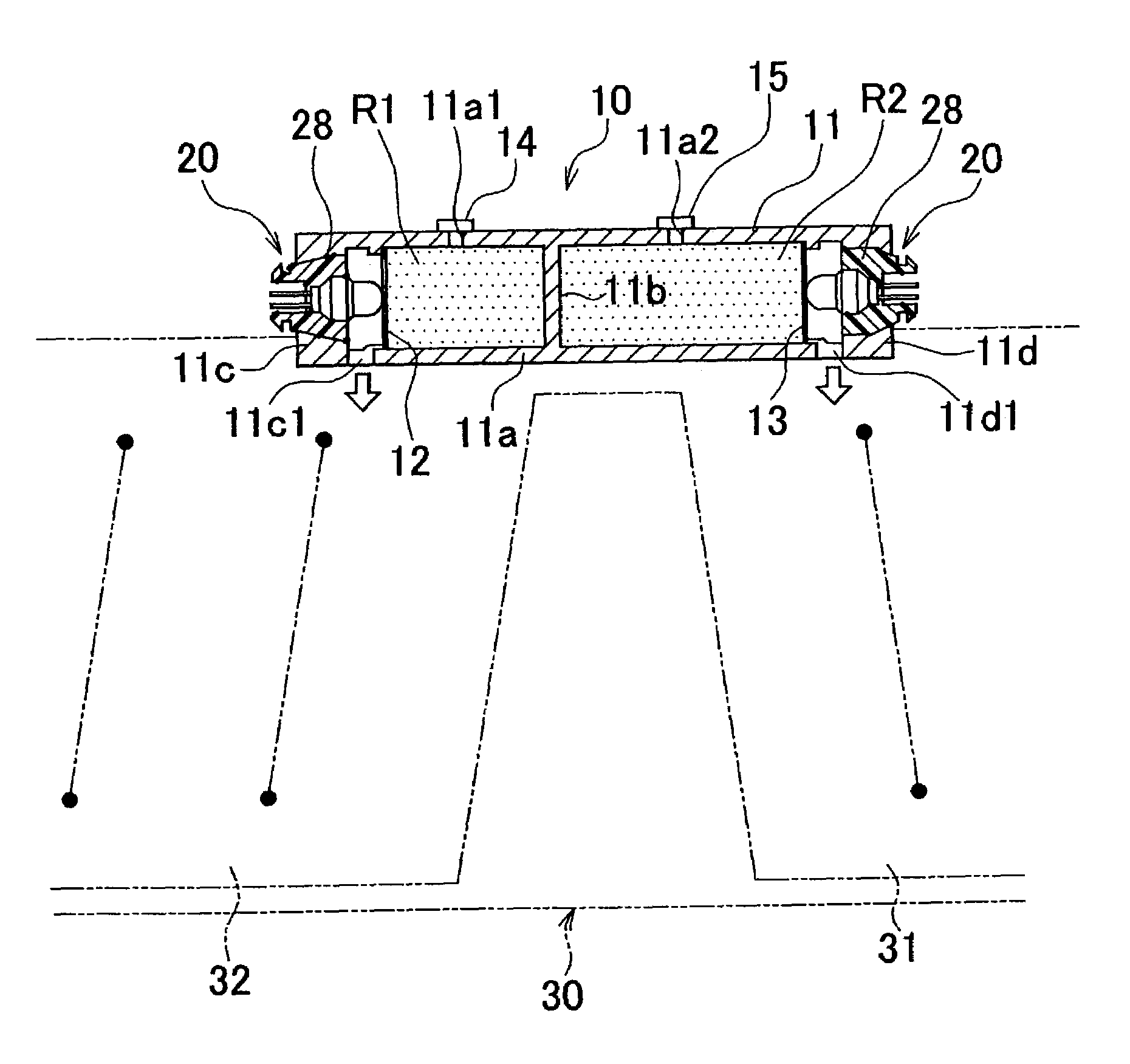
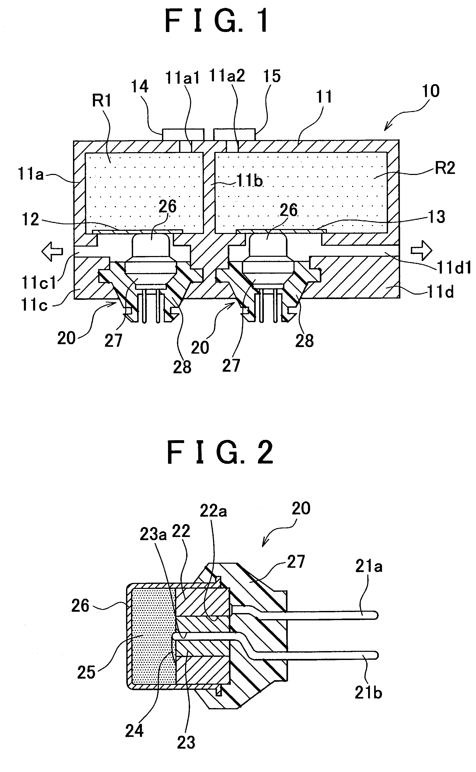
[0029]Hereinafter, the embodiments of the invention will be described with reference to the drawings. FIG. 1 schematically shows an inflator 10 in accordance with one embodiment of the invention. The inflator 10 of this embodiment includes a single casing 11, a pair of gas sealing plates 12, 13 mounted in the casing 11, and a pair of initiators 20.

[0030]The casing 11 has an outer wall 11a, an airtight partition 11b, and a pair of attachment portions 11c, 11d that also serve as part of the outer wall. The gas sealing plates 12, 13 and the initiators 20 are attached to the attachment portions 11c, 11d respectively. Gas feed passages 11c1, 11d1 are formed in the attachment portions 11c, 11d. A peripheral edge portion of the airtight partition 11b is integrally joined to the outer wall 11a and the attachment portions 11c, 11d. Thus, the airtight partition 11b is integrally formed in the casing 11 and airtightly separates a pair of small and large gas chambers R1, R2 from each other in t...


PUM


Abstract

In an inflator including a plurality of gas feed portions (gas chambers for storing high-pressure gases, gas sealing plates for sealing the gas chambers, and initiators for fracturing the gas sealing plates) in a single casing, an airtight partition integrated with the casing airtightly separates the gas chambers of the gas feed portions from each other, and the casing is provided with a plurality of gas feed passages that individually communicate with the gas chambers.

Description

INCORPORATION BY REFERENCE[0001]The disclosures of Japanese Patent Application No. 2002-111123 filed on Apr. 12, 2002, including the specification, drawings, and abstract is incorporated herein by reference in its entirety.BACKGROUND OF THE INVENTION[0002]1. Field of the Invention[0003]The invention relates to an inflator for expanding and deploying an air bag mounted in a vehicle or the like by supplying the air bag with gas.[0004]2. Description of the Related Art[0005]One inflator of this kind includes a plurality of gas feed portions in a single casing (also referred to as a housing), for example, as disclosed in Japanese Patent Application Laid-Open No. 11-217055. In an inflator disclosed in this publication, gas feed portions include gas chambers (combustion chambers) formed in a casing, gas generating agents accommodated in the gas chambers, filter members surrounding the gas generating agents in the casing, and initiators (igniters) for igniting and burning the gas generating...

Claims


Application Information

Patent Timeline
IPC IPC(8): B60R21/26B01J7/00B60R21/16B60R21/20B60R21/233B60R21/263B60R21/264B60R21/272
CPCB60R21/264B60R21/268B60R21/23138B60R21/232B60R2021/2685B60R2021/26058B60R2021/2633B60R2021/2648B60R2021/23332
Inventor TAKAHARA, ISAMU
Owner TOYOTA JIDOSHA KK
Why Eureka
Try Eureka