Adaptive threshold logic circuit

Inactive Publication Date: 2005-09-06
MICRON TECH INC
View PDF17 Cites 0 Cited by
  • Summary
  • Abstract
  • Description
  • Claims
  • Application Information

AI Technical Summary

Benefits of technology

[0005]The present invention provides a simple way of adjusting the switching threshold of a lo

Problems solved by technology

In such a case, the logic signals supplied to the first logic circuit are incompatible with the switching threshold of the fi

Method used


Image

  • Adaptive threshold logic circuit
  • Adaptive threshold logic circuit
  • Adaptive threshold logic circuit

Examples


Example

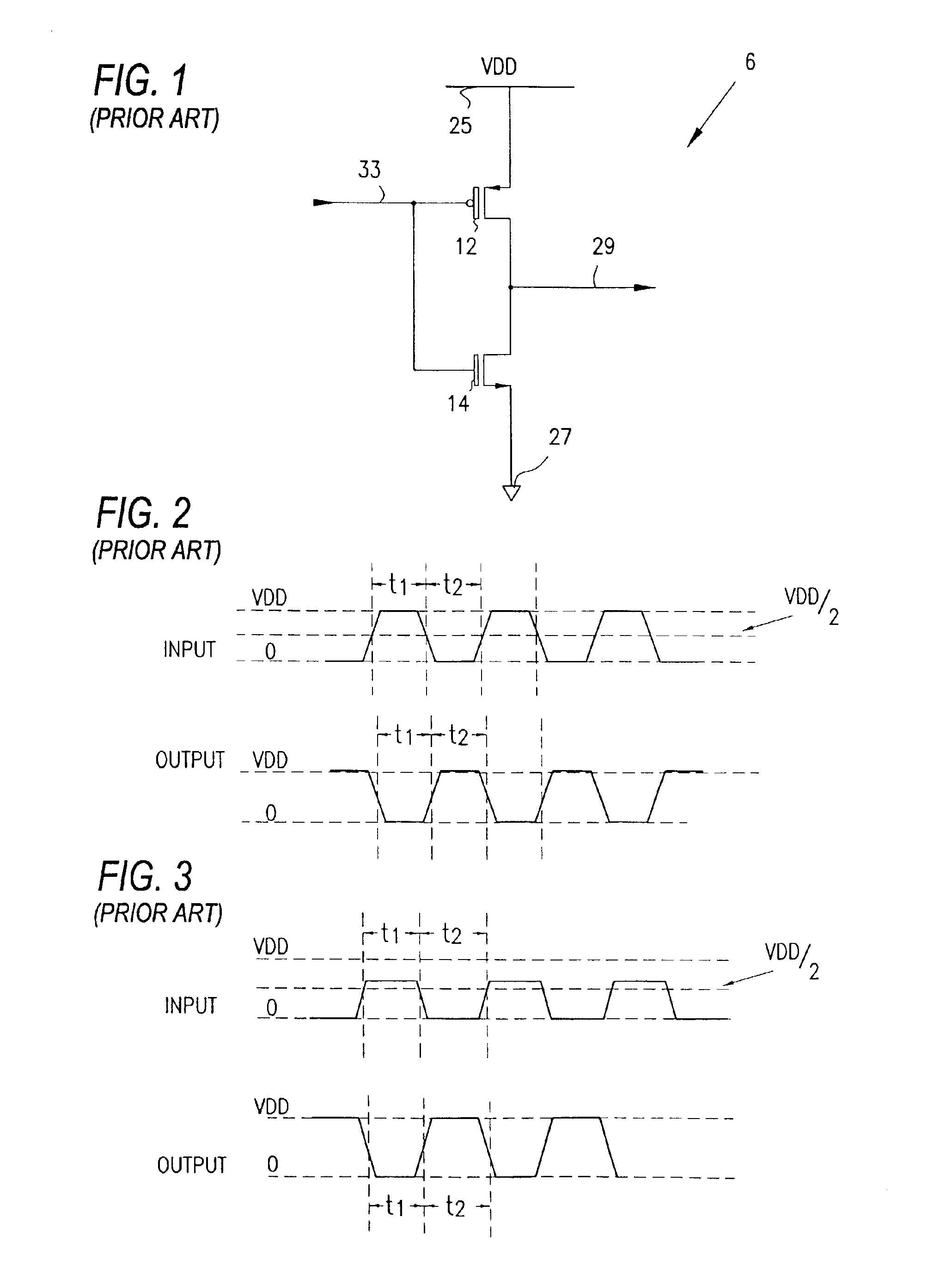
[0014]FIG. 1 is an electrical schematic drawing of a typical CMOS inverter 6 which switches states in response to switching states of logic signals applied to input line 33. The inverter 6 includes a p-channel MOS transistor 12 serially connected to an n-channel MOS transistor 14, with the serial connection of the two transistors being connected between VDD 25 and ground 27. The CMOS inverter 6 provides inverted output logic signals on line 29 in response to the states of logic signals applied to input line 33.

[0015]The transistors 12 and 14 are configured such that when VDD is at one voltage level, e.g., 3.3 volts, and the input logic signals on line 33 transition between voltage levels of zero and 3.3 volts, the inverted output signals on line 29 are likewise transitioning between 3.3 volts and zero volts with relatively low signal skew or waveform distortion because the switching threshold of transistors 12 and 14 is well matched to the expected zero to 3.3 volt transitions of th...


PUM


Abstract

An adaptive threshold logic circuit is provided in which the switching threshold levels of the logic circuit are automatically changed to accommodate variations in the level of applied data signals to the switching circuit. A detector stage detects the voltage level of the incoming data signals and selectively adjusts the threshold level of a threshold adaptor stage in accordance with the output of the detector stage. The threshold adaptor stage is essentially an adaptive CMOS inverter having various switching paths turned on or off in accordance with the output of the detector stage.

Description


Claims


Application Information

Patent Timeline
Owner MICRON TECH INC
Why Eureka
Try Eureka