Dental handpiece

a handpiece and dental technology, applied in dentistry, medical science, boring tools, etc., can solve the problems of inability to structurally incorporate the longitudinal axis of the handle body, the inability to use the instrument in the patient's mouth cavity, and the inability to use the coinciding axis of rotation and other problems, to achieve the effect of expanding the possibilities of use of the dental instrument and facilitating work

Inactive Publication Date: 2007-03-20
ROGOVSKY YURY MIKHAILOVICH
View PDF9 Cites 6 Cited by
  • Summary
  • Abstract
  • Description
  • Claims
  • Application Information

AI Technical Summary

Benefits of technology

[0009]Thus, the object of the present invention is to provide a dental handpiece with a swivel head which substantially does not extend outside the handpiece, thus making it possible to significantly expand possibilities of use of the dental instrument and significantly ease work therewith in a patient's mouth cavity. One more object of the present invention is to provide such a construction of the light guide, positioned inside the body, and the head of the dental handpiece, which makes possible to carry out a turn of the head in a seat of the body without subjecting the light guide to twisting or other potentially destroying actions. One more object of the instant invention is to provide a construction of a micromotor that is intended for use together with dental mechanical and also turbine handpieces that have a swivel head, virtually not extending outside the handpiece.
[0012]In the proposed dental handpiece, the gas feeding aperture to the turbine may be made in the form of a nozzle, one or several outlet apertures for the discharge of the gas turning the turbine may additionally be made in the head itself, and one or several intermediate channels for the discharge of that spent gas are made in the head mounting seat and in the body of the handpiece, this ensuring the discharge of gas from at least one outlet aperture in any position of the head when it is turned.
[0014]Additionally the use of means in the dental handpiece for securing the head in the seat is possible, this ensuring the rapid detachment and mounting or replacement of the head, which is convenient for sterilizing the head. In order to make use of the dental handpiece easier and to reduce the danger of trauma of the cavity being treated, the outer surface of the handpiece body around the seat of the head and also the outer surface of the head may be made in such a manner that together they form the shape of a body of rotation.
[0015]The dental instrument mounting means in the dental handpiece may comprise a device ensuring fixation and release of the instrument therein from the side of the working field. Miniaturization of the head itself is achieved by this, since in the traditionally used handpieces a button on top of the head is used to release the device in which the working instrument is mounted, which results in an increase of the longitudinal and lateral dimensions of the whole construction, reducing the convenience of working in the mouth cavity and increasing the danger of trauma to the patient.
[0021]The outlet of the first light guide and the inlet of the second light guide may be positioned on the axis of rotation of the head relative to the head mounting seat, and the head may have at least one output aperture, going through which air, turning the turbine, will blow on the outlet of the second light guide on the head, thus cleaning it of tooth dust and other impurities.

Problems solved by technology

A drawback of the known device is presence of the head body extending transversely to the handle-body and thus making the operation of the instrument in the patient's mouth cavity more complex.
An additional drawback of the known device is absence of a possibility for structural embodiment of coinciding axis of rotation of the dental instrument and longitudinal axis of the handle-body.
One more drawback of the known device is necessity to use a single light guide therein, which light guide passes through the handle inside the head what results in its twisting when the head turns, what may cause breaking of this light guide.
A drawback of existing micromotors is their limited functionality when used only with mechanical dental handpieces.

Method used


Image

  • Dental handpiece
  • Dental handpiece
  • Dental handpiece

Examples


Embodiment Construction

[0033]Reference will now be made in detail to the present preferred embodiments of the present invention, examples of which are illustrated in the accompanying drawings.

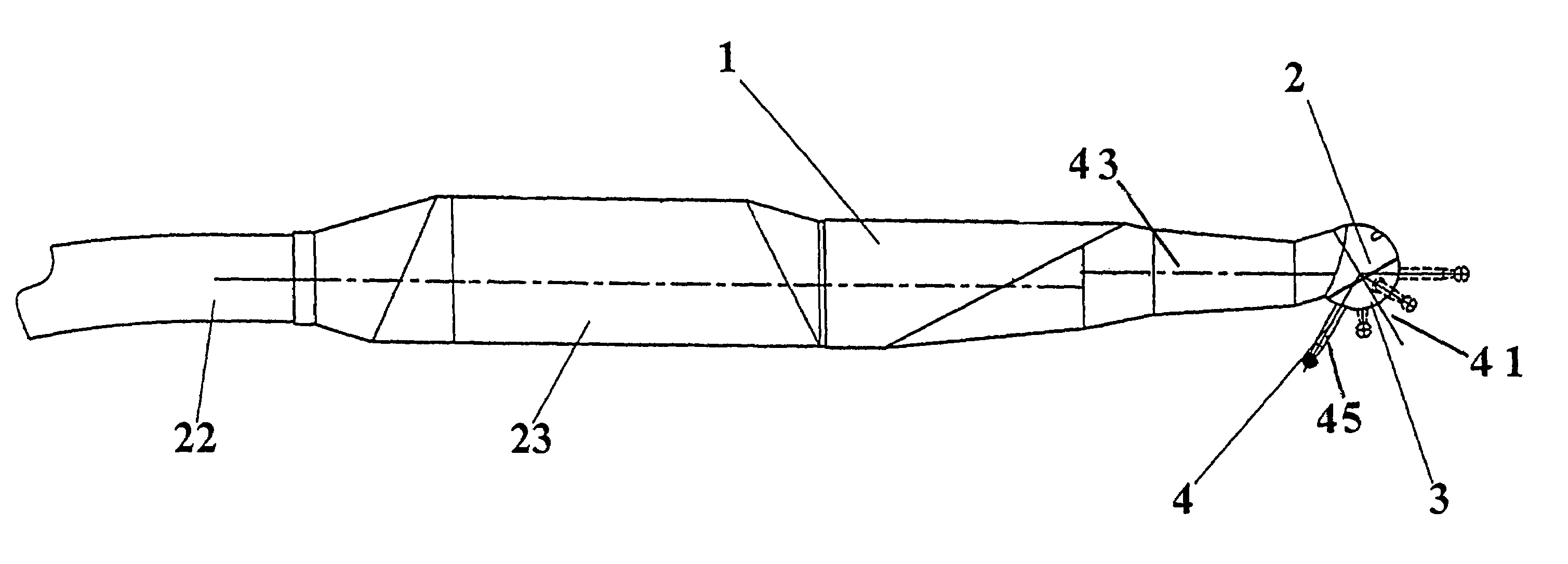
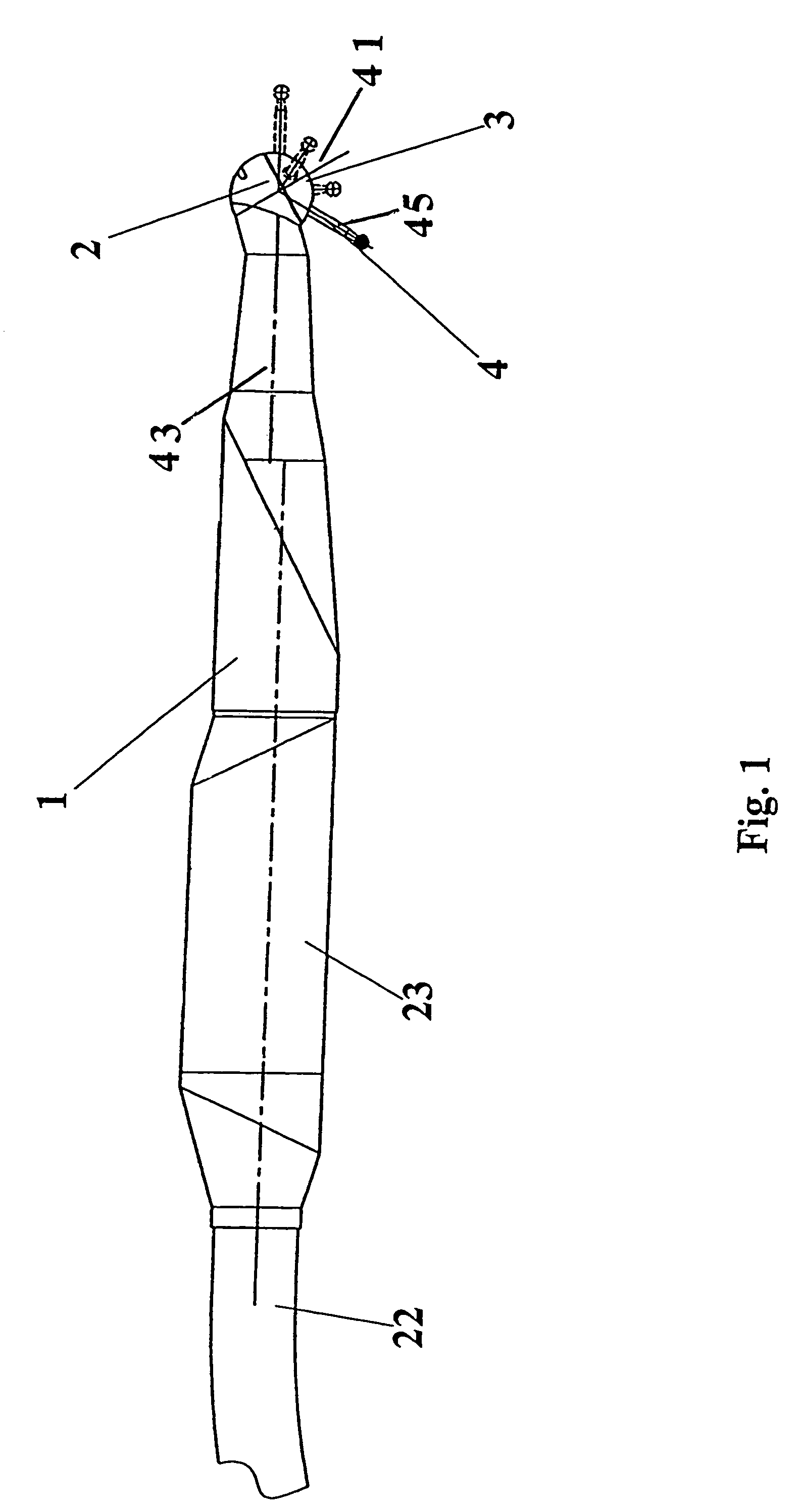
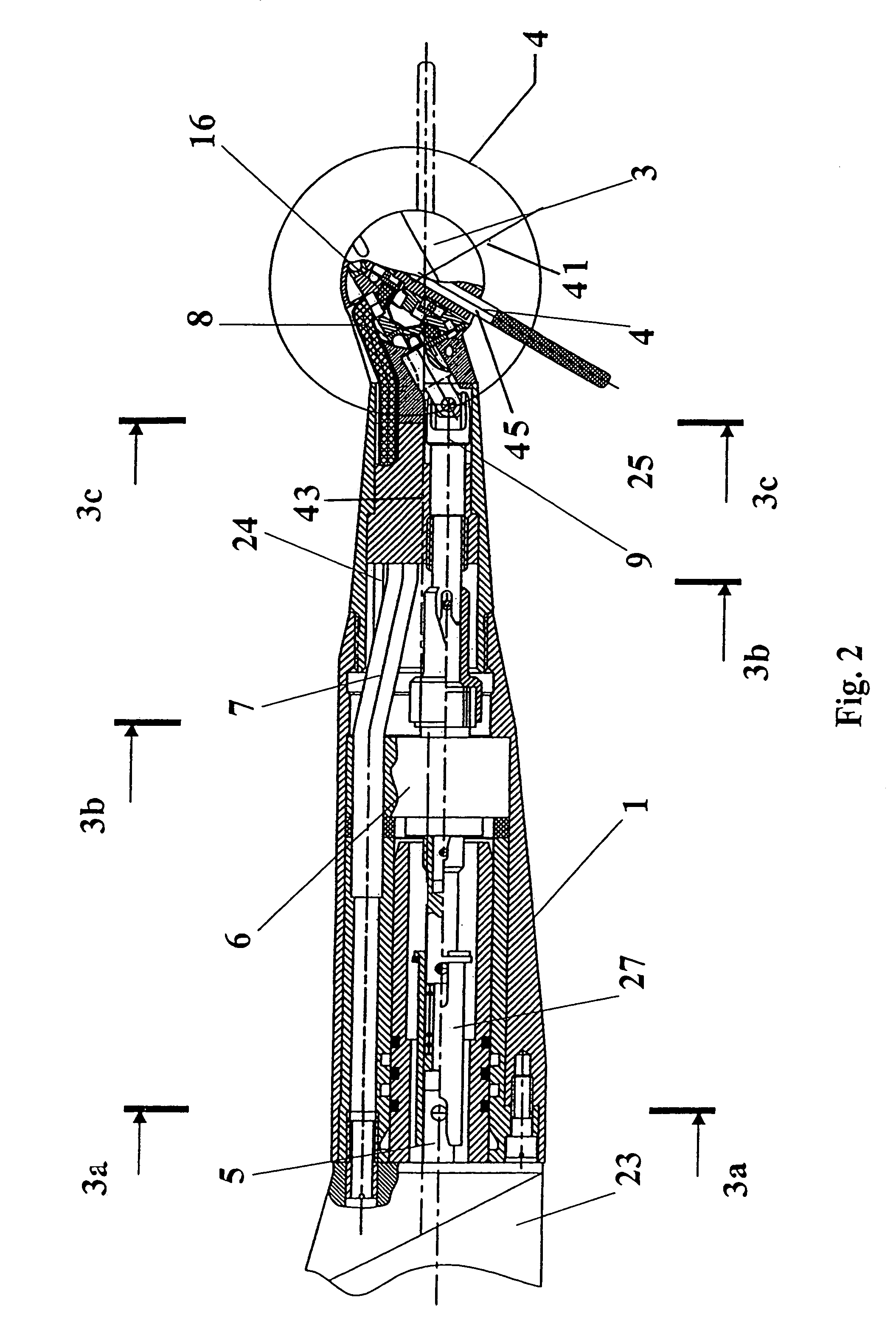
[0034]FIG. 1 presents a general view of a dental handpiece with an arm 22 and a body 23 for a micromotor 28 connected thereto. The dental handpiece has a body 1, terminating with a cup 2. There is a seat in the cup 2 of the body 1, in which seat a head 3 is turnably mounted for rotation about an axis 41. A dental instrument 4 is mounted in the head 3.

[0035]A specificity of the proposed dental handpiece is the virtually complete absence of transverse displacement of the head from the longitudinal axis 43 of the handpiece. Such a specificity makes it possible to provide a dental handpiece in which when there is a certain turn of the head 3 about axis of rotation 41, the longitudinal axis 45 of the dental instrument 4 coincides with the longitudinal axis 43 of the handpiece 1 itself.

[0036]It is desirable to made the out...


PUM


Abstract

A dental handpiece including a handpiece body with a head mounting seat, with a gas feeding channel, wherewith the seat is adapted to provide a full turn of the head. The head includes a turbine and an gas feeding aperture to the turbine. A micromotor is included having an inlet for feeding gas and a drive shaft for ensuring mechanical drive action. An intermediate gas feeding channel is made on the inner surface of the head mounting seat or on the outer surface of a part of the head. The drive shaft of the micromotor is connected to the head, and the inlet for feeding gas to the micrometer is connected to the gas feeding channel in the body.

Description

BACKGROUND OF THE INVENTION[0001]1. Field of the Invention[0002]The invention relates to medical equipment, in particular to dental handpieces.[0003]2. Description of the Related Art[0004]A dental handpiece is known from RU patent 2030904, issued Mar. 20, 1995. This dental handpiece comprises a handle-body with channels arranged therein for supply and discharge of air, a head with a body extending sidewise from the handle-body, the head being mounted with the possibility for turning in a sagital plane by 360° C. by means of a turning sleeve arranged in the handle-body of the handpiece and entering into engagement on one side with a screw drive mounted on the handle-body, and on the other side with a pinion connected to the body of the head, a turbine arranged in the head and mounted on bearings. The dental instrument in the known handpiece is mounted in a collet holder connected to the turbine and having therewith a common axis of rotation. The known device additionally comprises a ...

Claims


Application Information

Patent Timeline
Patent Type & Authority Patents(United States)
IPC IPC(8): A61C1/12A61C1/05A61C1/08A61C1/10
CPCA61C1/05A61C1/12A61C1/10A61C1/088
Inventor ROGOVSKY, YURY MIKHAILOVICH
Owner ROGOVSKY YURY MIKHAILOVICH
Why Eureka
Try Eureka