

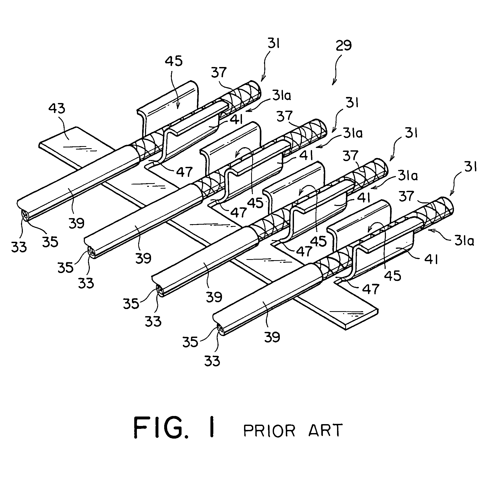
Cable with a meandering portion and a ground portion sandwiched between retaining elements
a technology of retaining elements and cables, applied in the field of cables, can solve the problems of affecting the service life of the cable, the bendability of the fine coaxial cable is degraded in the range of solder raised, and the connection failure is liable to occur likewise, so as to achieve the effect of not degrading the bendability of the cable and being readily ben
- Summary
- Abstract
- Description
- Claims
- Application Information
AI Technical Summary
Benefits of technology
Problems solved by technology
Method used
Image

Examples
first embodiment
[0061]Referring to FIGS. 4 to 6, a connector 71 according to this invention comprises a metal shell 73 being a metal outer member, a connector body 75, and a cable line-up member 77. In the following description, similar parts being described will be represented by similar reference numerals.
[0062]As best shown in FIG. 5, the connector body 75 comprises an insulator 79. The insulator 79 is provided on its side, i.e. at a lower end in FIG. 5, with a fitting portion 87 for receiving therein a counterpart connector. The fitting portion 87 has recessed portions 81 and 83 and a projected stripe portion 85 therebetween. Further, on the other side, the insulator 79 has a cable receiving portion 89 for receiving therein one end of the cable line-up member 77. The insulator 79 is provided with contacts 95 each having a U-shape in section and each comprising a cable contacting portion 91, a contact contacting portion 93, and a tip end portion 96 that are formed integral with each other. Each ...
third embodiment
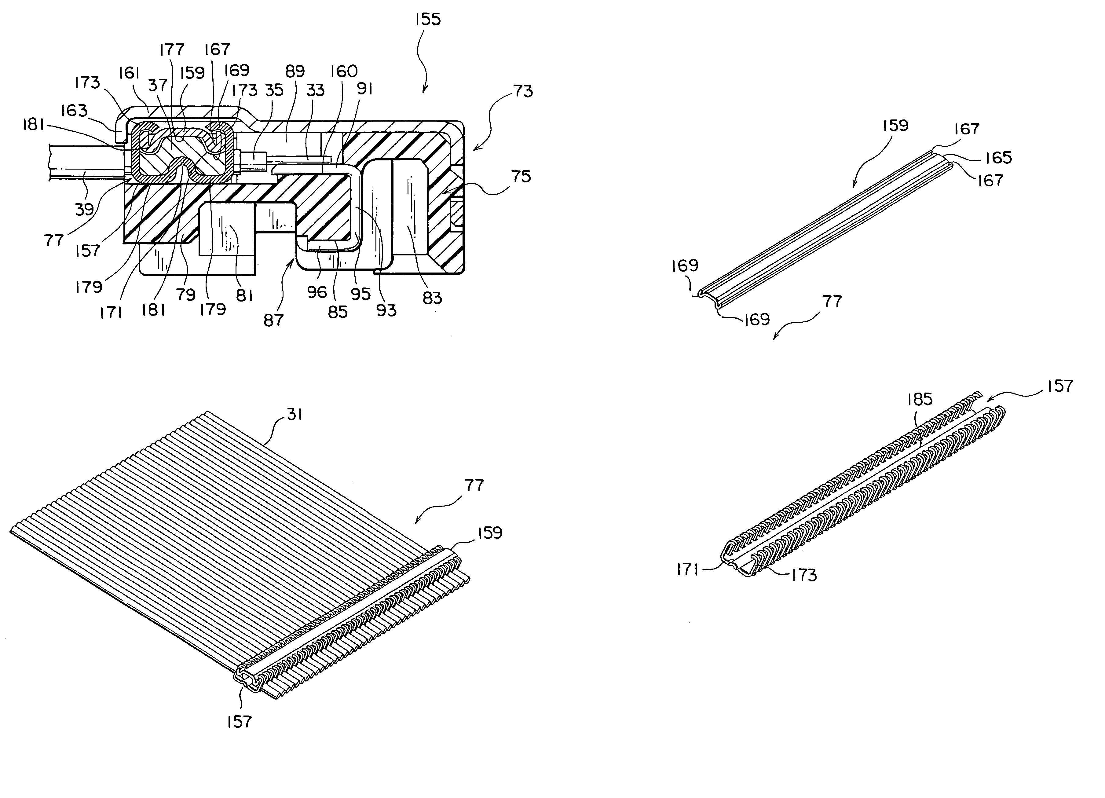
[0080]FIG. 15 is a perspective view of a connector according to this invention. FIG. 16 is a sectional view of the connector shown in FIG. 15.
[0081]Referring to FIGS. 15 and 16, a connector 155 comprises the metal shell 73 being a metal outer member, the connector body 75, and the cable line-up member 77 having a lower metal plate 157 and an upper metal plate 159.
[0082]As best shown in FIG. 16, the connector body 75 comprises the insulator 79. The insulator 79 is provided on its side, i.e. at a lower end in FIG. 16, with the fitting portion 87 for receiving therein a counterpart connector. The fitting portion 87 has recessed portions 81 and 83 and the projected stripe portion 85 therebetween. Further, on the other side, the insulator 79 has the cable receiving portion 89 for receiving therein one end of the cable line-up member 77. The insulator 79 is provided with contacts 95 each having a U-shape in section and each comprising the cable contacting portion 91, the contact contactin...
second embodiment
[0084]The shell 73 is formed with a platform 161 raised in a stepped fashion on an opening side. The platform 161 has a front end bent vertically to form a presser strip 163 on the front side. The presser strip 163 is shorter in vertical length than the presser strip 130 in the second embodiment but still has the same effect of preventing the cable line-up member 77 from coming off as described before.
[0085]Referring to FIG. 17A, the cable line-up member 77 comprises the lower metal plate 157, the upper metal plate 159, and fine coaxial cables 31 sandwiched between the lower metal plate 157 and the upper lower plate 159. Herein, the lower metal plate 157 and the upper metal plate 159 are collectively called a cable retaining member wherein the lower metal plate 157 is called a first retaining element and the upper metal plate 159 is called a second retaining element.
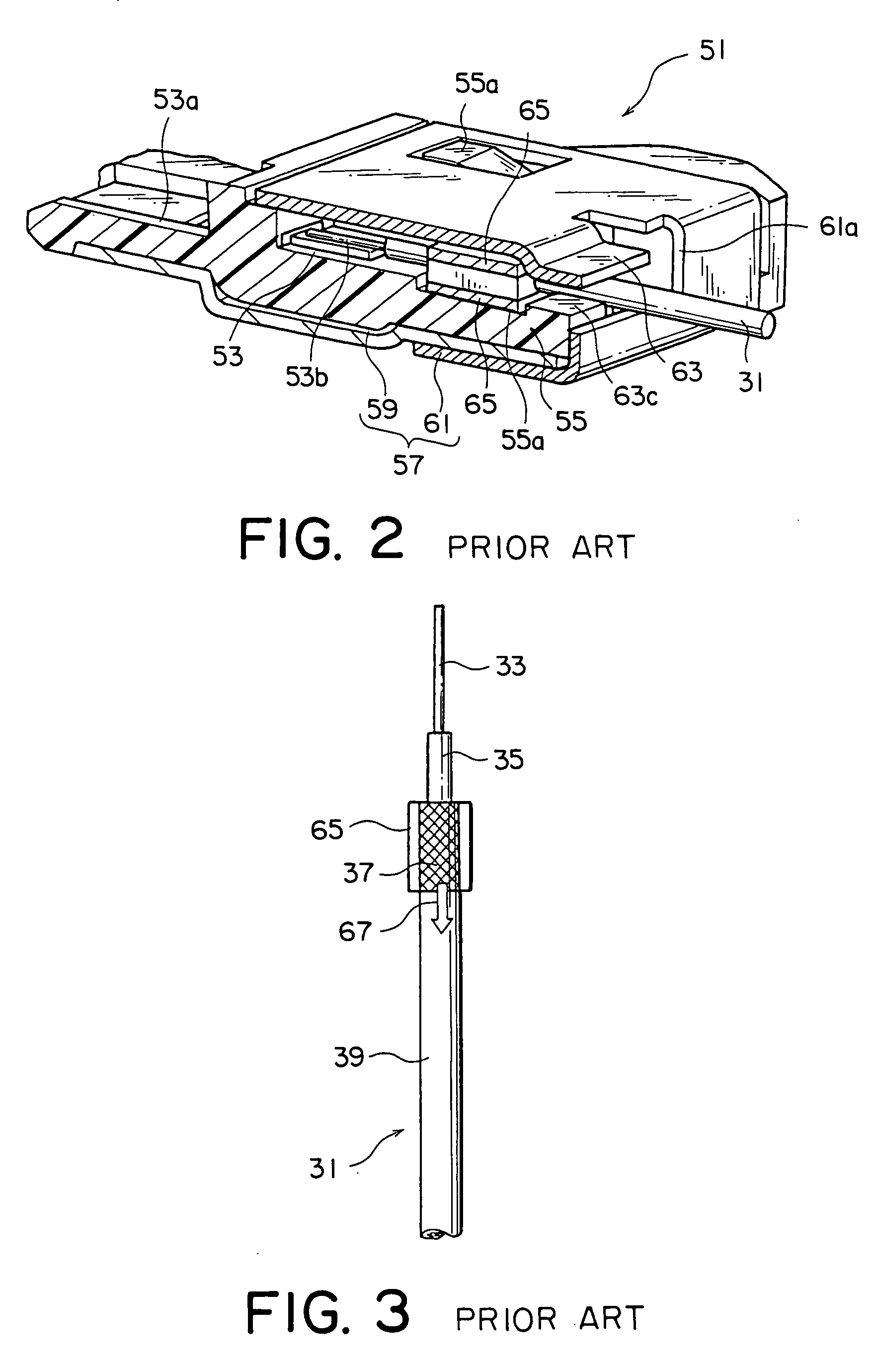
[0086]In the illustrated example, each of the fine coaxial cable 31 has one end portion where the jacket 39 is removed...
PUM
 Abstract
Description
Claims
Application Information