Electrical connector

a technology of electrical connectors and shield materials, applied in the direction of electrical apparatus, connection, coupling device connection, etc., can solve the problems of troublesome wiring operations for the unnecessary second terminal, and achieve the effect of easy electrically connecting shield materials

Inactive Publication Date: 2007-03-20
JST MFG CO LTD
View PDF2 Cites 18 Cited by
  • Summary
  • Abstract
  • Description
  • Claims
  • Application Information

AI Technical Summary

Benefits of technology

[0006]A main object of the invention is to provide a connector and a cable retainer which can easily electrically connect a cable shield material and an electrode as a connection destination.
[0009]According to the invention, a shield material of the cable and the second terminal can be electrically connected by an easy method in that the shield material and the first projection are electrically connected and the second projection and the second terminal (electrode) are electrically connected. Therefore, the troublesome wiring operations for electrically connecting the shield material and the second terminal become unnecessary. Accordingly, harness manufacturing costs can be reduced.
[0010]In addition, according to the invention, it is preferable that the first projection is plastically deformed by caulking to clip the cable disposed on the main part between the first projection and the main part. Thereby, various types of the cable with different diameters can be securely retained.

Problems solved by technology

Therefore, the troublesome wiring operations for electrically connecting the shield material and the second terminal become unnecessary.

Method used


Image

  • Electrical connector
  • Electrical connector
  • Electrical connector

Examples


Embodiment Construction

[0026]Hereinafter, a connector according to a preferred embodiment of the invention is described with reference to the drawings.

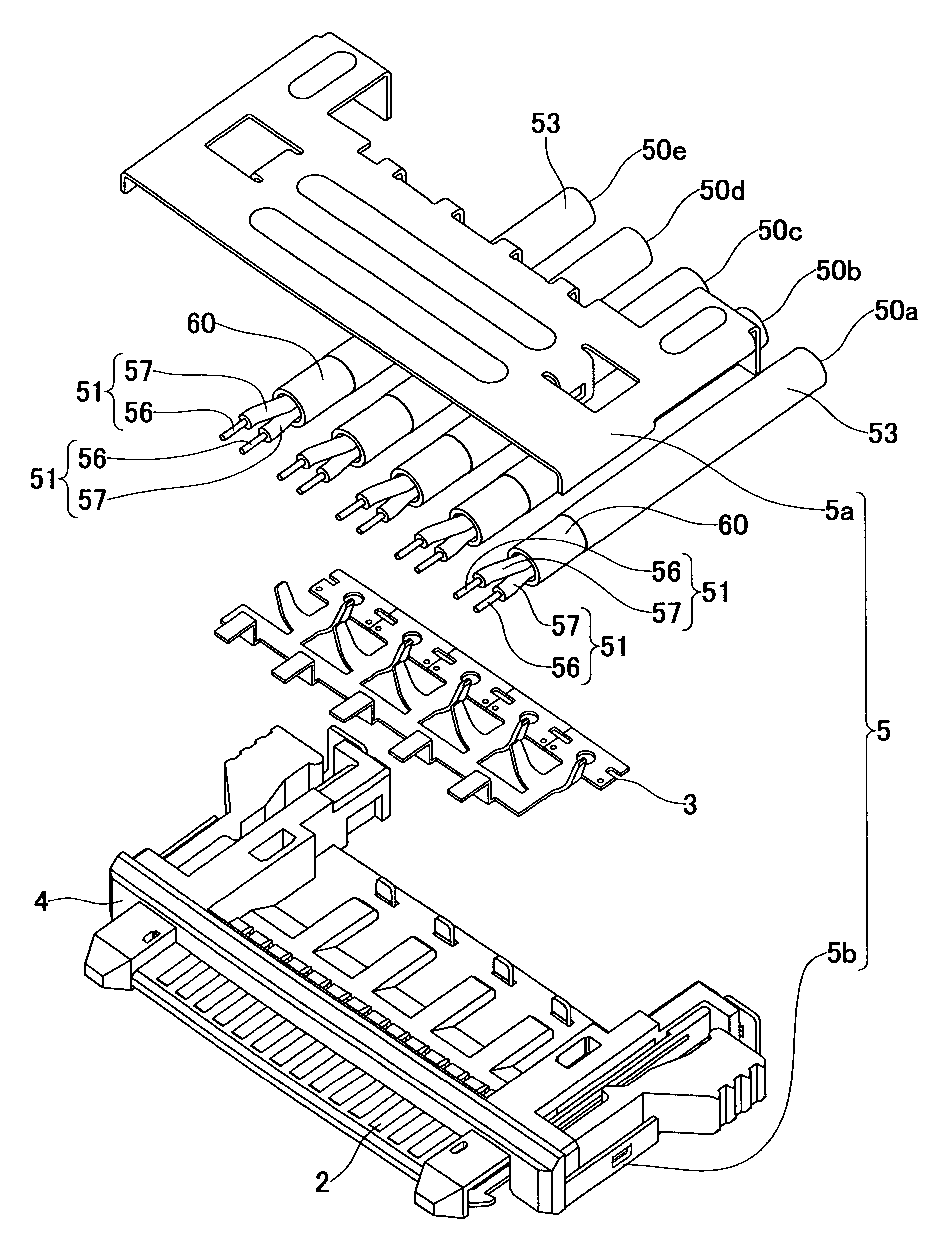
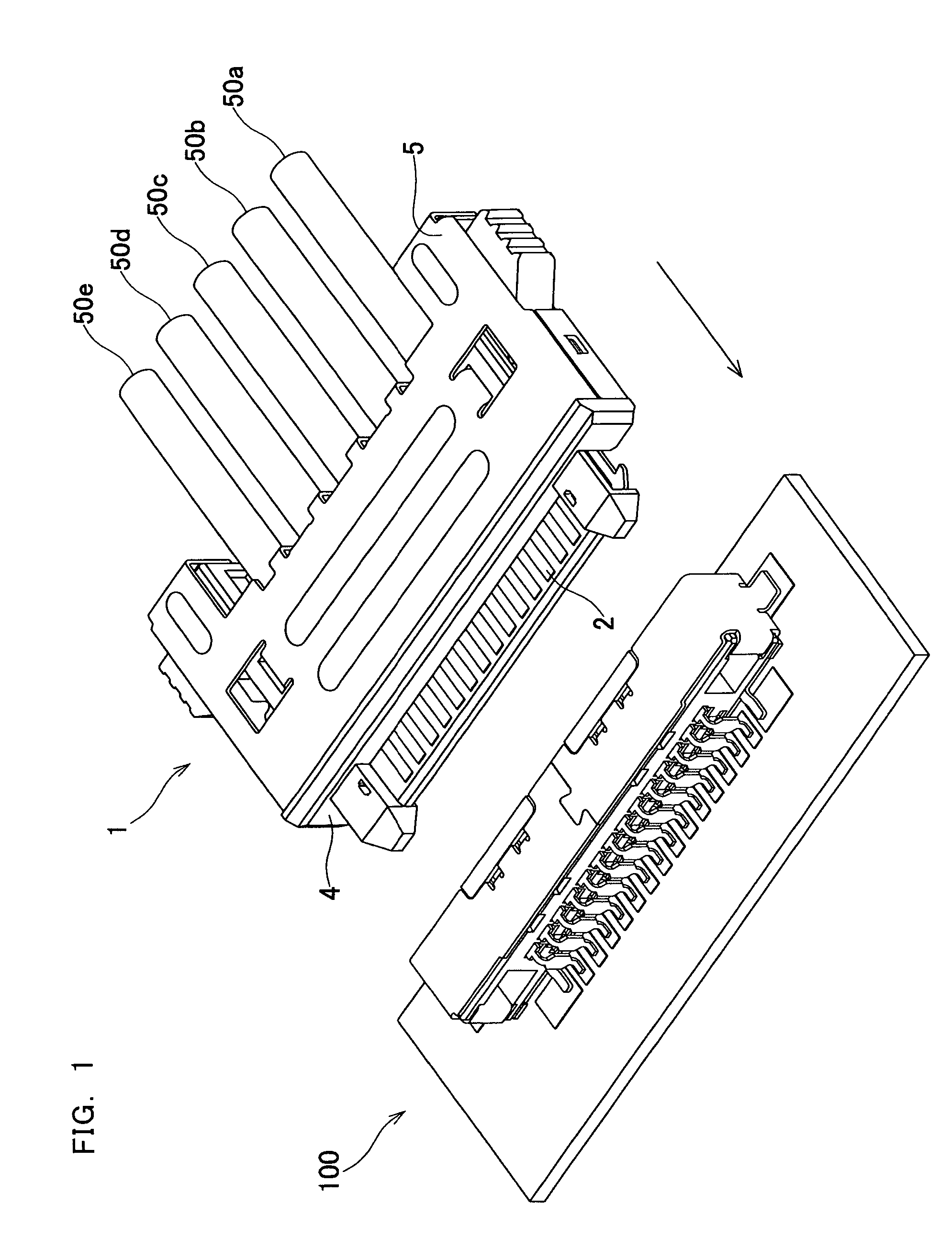
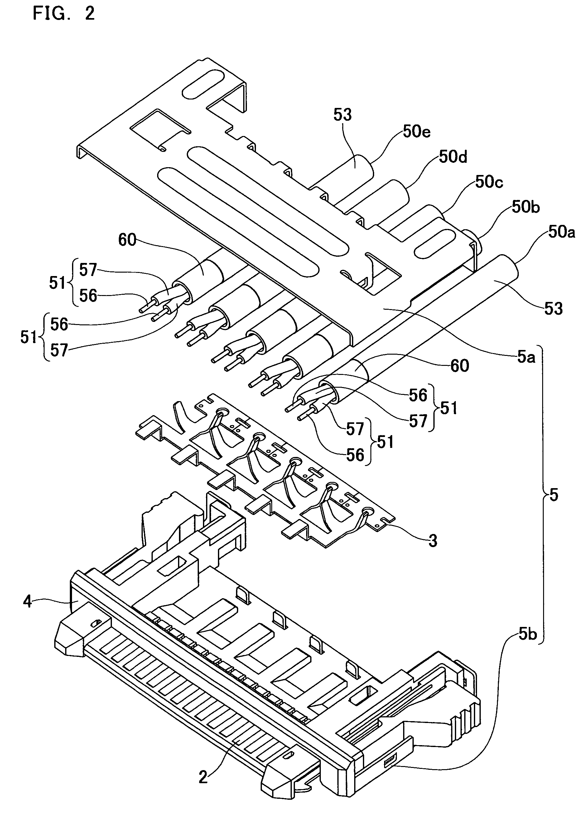
[0027]FIG. 1 is a perspective view of a connector according to a preferred embodiment of the invention and the opposing connector which said connector is inserted into and extracted from. The arrow in the figure indicates the inserting direction of the connector 1 into the opposing connector 100. FIG. 2 is an exploded perspective view of the connector 1. As shown in FIG. 1, to the connector 1, five cables 50a through 50e are connected, and the connector can be inserted into and extracted from the opposing connector 100. The connector 1 includes fourteen terminals (first terminals and second terminals) 2 that are aligned at a predetermined pitch in a direction orthogonal to the inserting direction of the connector 1, a cable retainer 3, and a housing (supporter) 4.

[0028]As shown in FIG. 2, the terminals 2 are thin plate-shaped electrodes extending along the ...


PUM


Abstract

A connector is provided with a cable retainer which includes thin plate extending in one direction, five projections projecting from the thin plate part, and a ground part projecting from the projections. The cable retainer clips cables by projections plastically deformed by caulking. Furthermore, when the cable retainer is attached to a housing, it is arranged so that the ends of the connect portions of the ground part face the terminals that serve as ground electrodes.

Description

BACKGROUND OF THE INVENTION[0001]1. Field of the Invention[0002]The present invention relates to a connector and a cable retainer to which a cable with a shield material is connected.[0003]2. Description of Related Art[0004]In order to realize higher speed signal processing, high-frequency signals have been propagated in a device or between devices. Some cables preferable for propagating high-frequency signals include a signal wire for propagating high-frequency signals and a conductive shield material enclosing the outer circumference of the signal wire. By grounding the shield material, high-frequency signals propagating in the signal wire can be protected from noises. A technique (refer to Japanese Published Unexamined Patent Application No. H11-260439) is known in that, in a connector to which a shield material-attached cable is connected, the shield material is exposed to the outer circumference of the cable, and the exposed shield material is clipped by a conductive terminal, ...

Claims


Application Information

Patent Timeline
Patent Type & Authority Patents(United States)
IPC IPC(8): H01R12/24
CPCH01R9/032H01R13/6592H01R13/65807H01R13/6589H01R13/6275H01R4/023H01R4/184H01R13/65912H01R13/639
Inventor KURODA, KEIJIMORIWAKE, RYOARAMOTO, KIYOSHI
Owner JST MFG CO LTD
Why Eureka
Try Eureka