Laser scanner and method for optically scanning an environment

a laser scanner and optical scanning technology, applied in the direction of reradiation, distance measurement, instruments, etc., can solve the problems of inability to produce image recordings of an environment through the known procedure, the receiver is not available which covers such a wide dynamic range, and the known device and the known method are thus limited for measurements, so as to reduce transmission power, reduce imaging errors, the effect of increasing or reducing transmission power

Active Publication Date: 2007-03-20
FARO TECH INC
View PDF10 Cites 116 Cited by
  • Summary
  • Abstract
  • Description
  • Claims
  • Application Information

AI Technical Summary

Benefits of technology

[0012]The new scanner and method allow for a generally reduced transmission power and a high-quality reproduction of the environment of the laser scanner in a half tone representation. For varying distances and / or varying reflectivity of the measurement points, imaging errors are avoided by the transmission power being increased or reduced. Since the transmission power is taken into account in the formation of the gray-scale value, the measurement error systematically generated by the adjustment of the transmission power is precisely “calculated out” again, so that an unaltered faithful image of the environment is generated as a halftone representation.
[0013]For measurement points that are further away and / or weakly reflective, the transmission power is increased in order that the reflected signal still has a sufficient magnitude so as not to overtax the dynamic range of the receiver. Conversely, the transmission power can also be reduced in the case of very close and / or strongly reflective measurement points. This contrivance therefore makes possible, in a relatively simple manner, a reliable measurement even with large distance and / or gray-scale value ranges, without an excessive outlay having to be implemented for the receiver or actually overtaxing the possibilities of commercially available receivers. Furthermore, by limiting the transmission power, a lower energy consumption is made possible and persons in the vicinity of the scanner are reliably protected against injury, in particular eye injury.
[0015]This measure has the advantage that even receivers having a very small dynamic range and therefore having very low costs can be used.
[0017]This measure has the advantage that, using simple circuitry means, it becomes possible to set the transmission power for a varying intensity of the reflected measurement beam, in which case the characteristic curve of the characteristic curve stage can be assigned in a manner dependent on the physical conditions such that the function of the intensity or the power of the emitted light beam against the intensity of the reflected measurement beam becomes substantially linear, if not even at least approximately constant.
[0019]This allows a practical implementation with simple circuitry. The second characteristic curve stage makes possible a complete compensation of the adjustment of the transmission power as a function of the intensity of the reflected light beam.

Problems solved by technology

According to the current prior art there are no receivers available which cover such a wide dynamic range.
The known device and the known method are thus limited for measurements at a single measurement point, because the measurement point has to be intrinsically optimized in each case by adjusting the transmission power and / or the reception gain.
Therefore, image recordings of an environment cannot be produced by means of the known procedure.

Method used


Image

  • Laser scanner and method for optically scanning an environment
  • Laser scanner and method for optically scanning an environment

Examples


Embodiment Construction

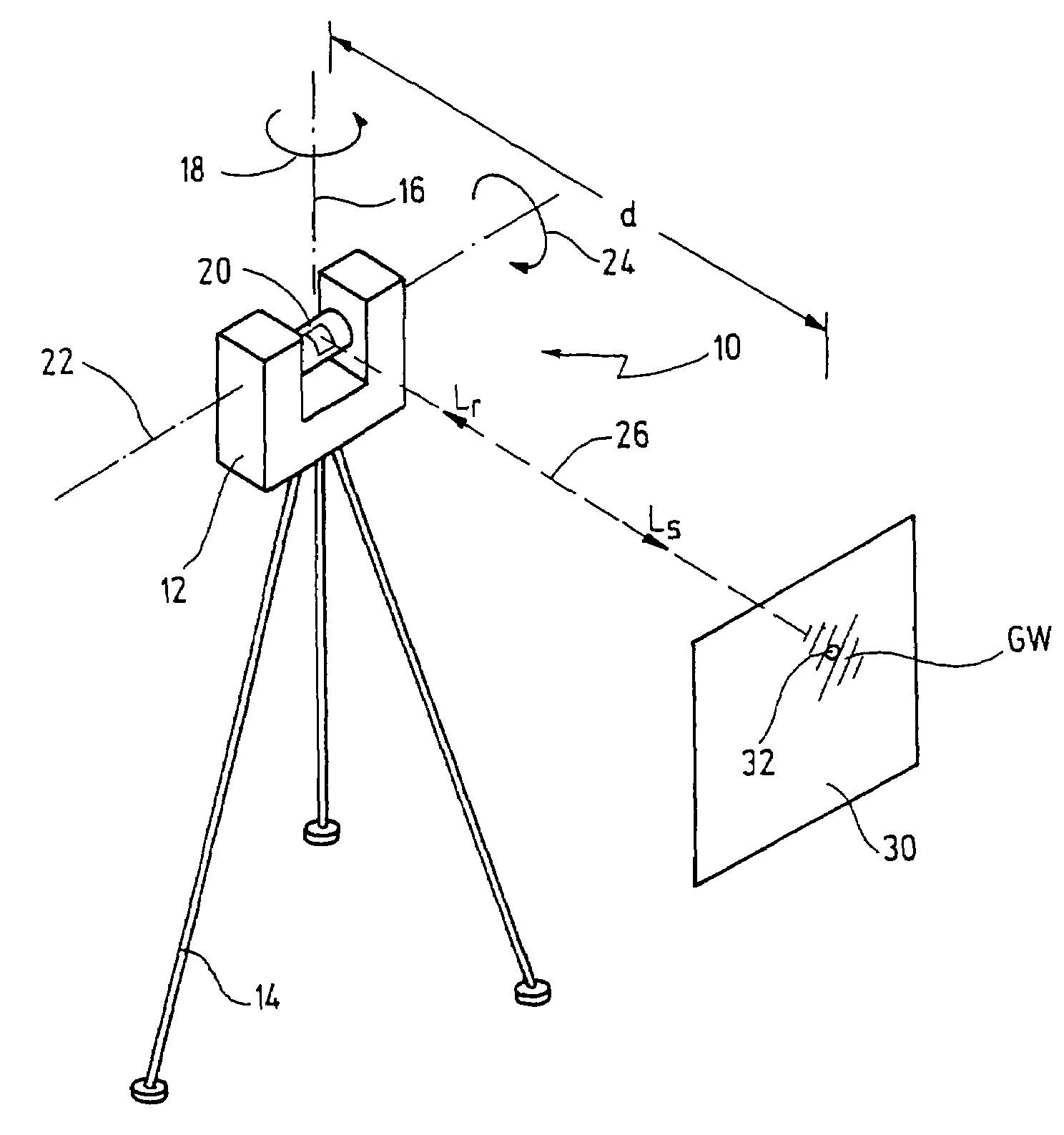
[0024]In FIG. 1, reference numeral 10 designates a laser scanner for the optical scanning and measurement of an environment of the laser scanner 10. In an exemplary embodiment illustrated in FIG. 1, an image of the environment with a solid angle of ideally 360° is intended to be generated from a static point.

[0025]For this purpose, the laser scanner 10 contains a measuring head 12 situated on a spatially fixed stand 14. In this case, the measuring head 12 is rotatable as a whole relatively slowly about a vertical axis 16, as indicated by an arrow 18.

[0026]The measuring head 12 contains, for its part, a rotor 20, which is rotatable significantly faster, that is to say at a significantly higher rotation speed, about a horizontal axis 22, as indicated by an arrow 24.

[0027]The rotor 20 emits a light beam 26. In FIG. 1, the beam emitted by the rotor 20 is designated by Ls, while a beam reflected from an object 30 in the environment is indicated by Lr.

[0028]In the situation illustrated in...


PUM


Abstract

A laser scanner for optically scanning and measuring an environment comprises a light transmitter having a predetermined transmission power for emitting a light beam. The emitted light beam is reflected at a measurement point in the environment. The reflected light beam is received with a certain intensity by a receiver. The transmission power is adjustable as a function of the intensity of the reflected light beam. Furthermore, a gray-scale value of the measurement point is determined as a function of the transmission power adjusted.

Description

CROSS-REFERENCE TO RELATED APPLICATIONS[0001]This is a continuation of international patent application PCT / EP2004 / 014605 filed on Dec. 22, 2004 and published in German language as WO 2005 / 064273 A1, which international patent application claims priority from German patent application DE 103 61 870.8 filed on Dec. 29, 2003.BACKGROUND OF THE INVENTION[0002]The invention relates to a laser scanner and a method for optically scanning and measuring an environment. More particularly, the invention relates to laser scanners used to scan and measure a variety of interior and exterior spaces. For instance, these may be manufacturing buildings in which specific facilities are planned. In this case, the laser scanner is placed on a stand into the space to be measured, and the measuring head is slowly rotated about a vertical axis, while a rotor—arranged in the measuring head—with a light transmitter rotates at a significantly higher rotational speed about a horizontal axis. In this way, the f...

Claims


Application Information

Patent Timeline
Patent Type & Authority Patents(United States)
IPC IPC(8): G01C3/00G01B11/24G01C15/00G01S7/489G01S7/497G01S17/36G01S17/89
CPCG01C15/002G01S7/4918G01S17/89G01S17/36G01S7/497
Inventor OSSIG, MARTINBECKER, REINHARDBECKER, BERND-DIETMAR
Owner FARO TECH INC
Why Eureka
Try Eureka