Magnetic head having heat sink structure

a heat sink and magnetic head technology, applied in the field of magnetic heads, can solve the problems of increasing the risk of heat damage to delicate pole tips and magnetoresistive sensor structures, the development and use of ever smaller and increasingly delicate magnetic pole tips, and the generation of electrical current within the induction coil

Inactive Publication Date: 2007-03-20
WESTERN DIGITAL TECH INC
View PDF2 Cites 21 Cited by
  • Summary
  • Abstract
  • Description
  • Claims
  • Application Information

AI Technical Summary

Benefits of technology

[0007]Further embodiments of the invention include the fabrication of a second heat sink beneath the first magnetic pole, and the fabrication of thermal interconnects between the two heat sinks, and the fabrication of a thermal interconnect to the slider body for enhanced thermal dissipation.
[0008]It is an advantage of the magnetic head of the present invention that a heat sink is provided to protect sensitive components of the magnetic head from excessive operational heat.
[0009]It is another advantage of the magnetic head of the present invention that the fabrication of the heat sink is accomplished subsequent to the fabrication of delicate components of the magnetic head.
[0010]It is a further advantage of the magnetic head of the present invention that the pre-existing process for fabricating the delicate components of the magnetic head is not altered by the fabrication of the heat sink.
[0011]It is an advantage of the hard disk drive of the present invention that it includes a magnetic head of the present invention in which a heat sink is provided to protect sensitive components of the magnetic head from excessive operational heat.
[0012]It is an advantage of the process for fabricating a magnetic head of the present invention that the heat sink is fabricated in the same fabrication steps for the creation of the electrical leads to the induction coil of the magnetic head.

Problems solved by technology

The ongoing effort to increase the areal data storage density of the hard disk drive results in the development and usage of ever smaller and increasingly delicate magnetic pole tips and magnetoresistive sensors for writing and reading increasingly smaller data bits onto the disk.
As is well known, the data writing process involves the use of an induction coil to generate magnetic fields within the magnetic poles of the write head, and the electrical current within the induction coil generates a significant amount of heat.
The delicate pole tips and magnetoresistive sensor structures are increasingly susceptible to heat caused malfunction and damage as the size of these structures is diminished.

Method used


Image

  • Magnetic head having heat sink structure
  • Magnetic head having heat sink structure
  • Magnetic head having heat sink structure

Examples


first embodiment

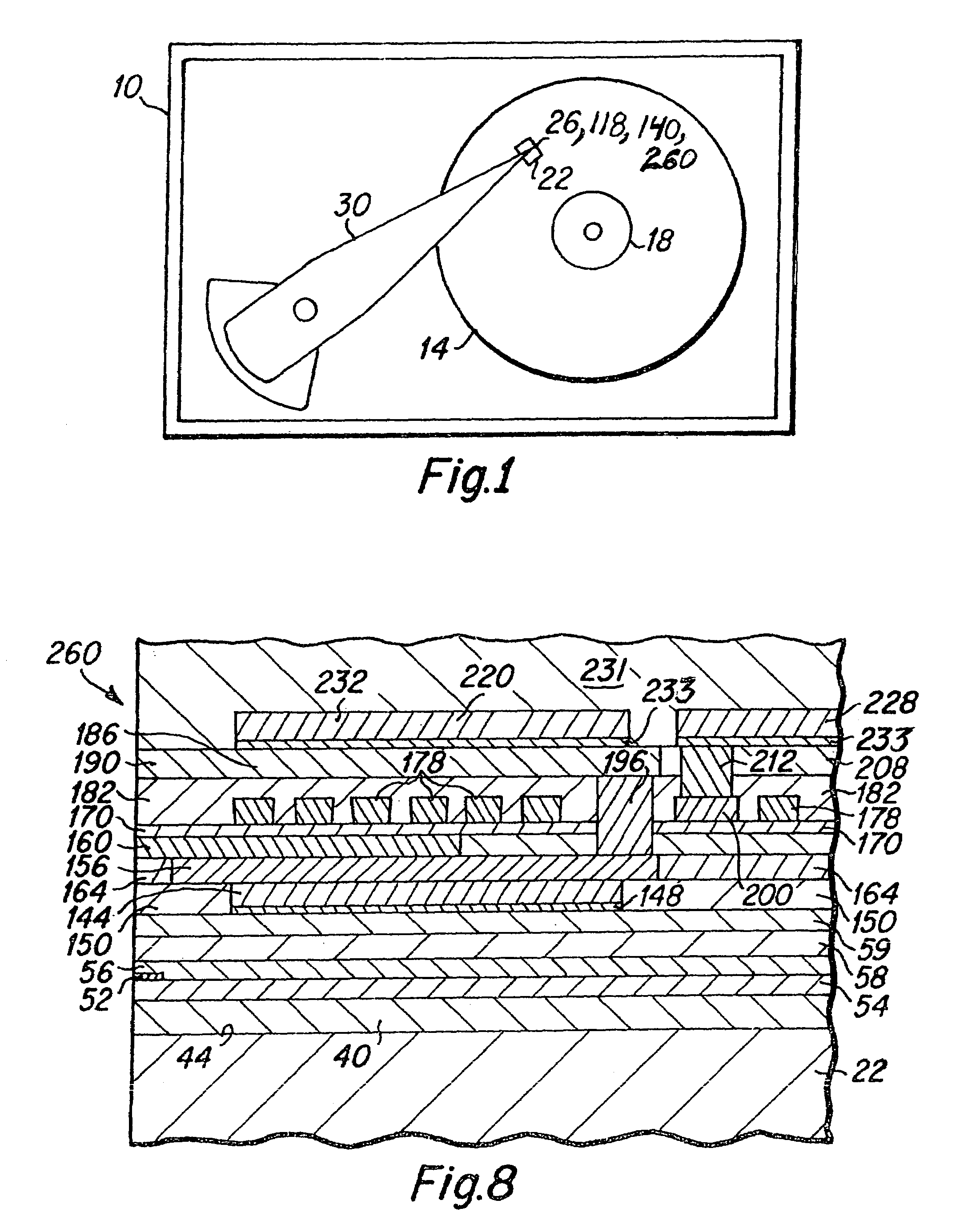
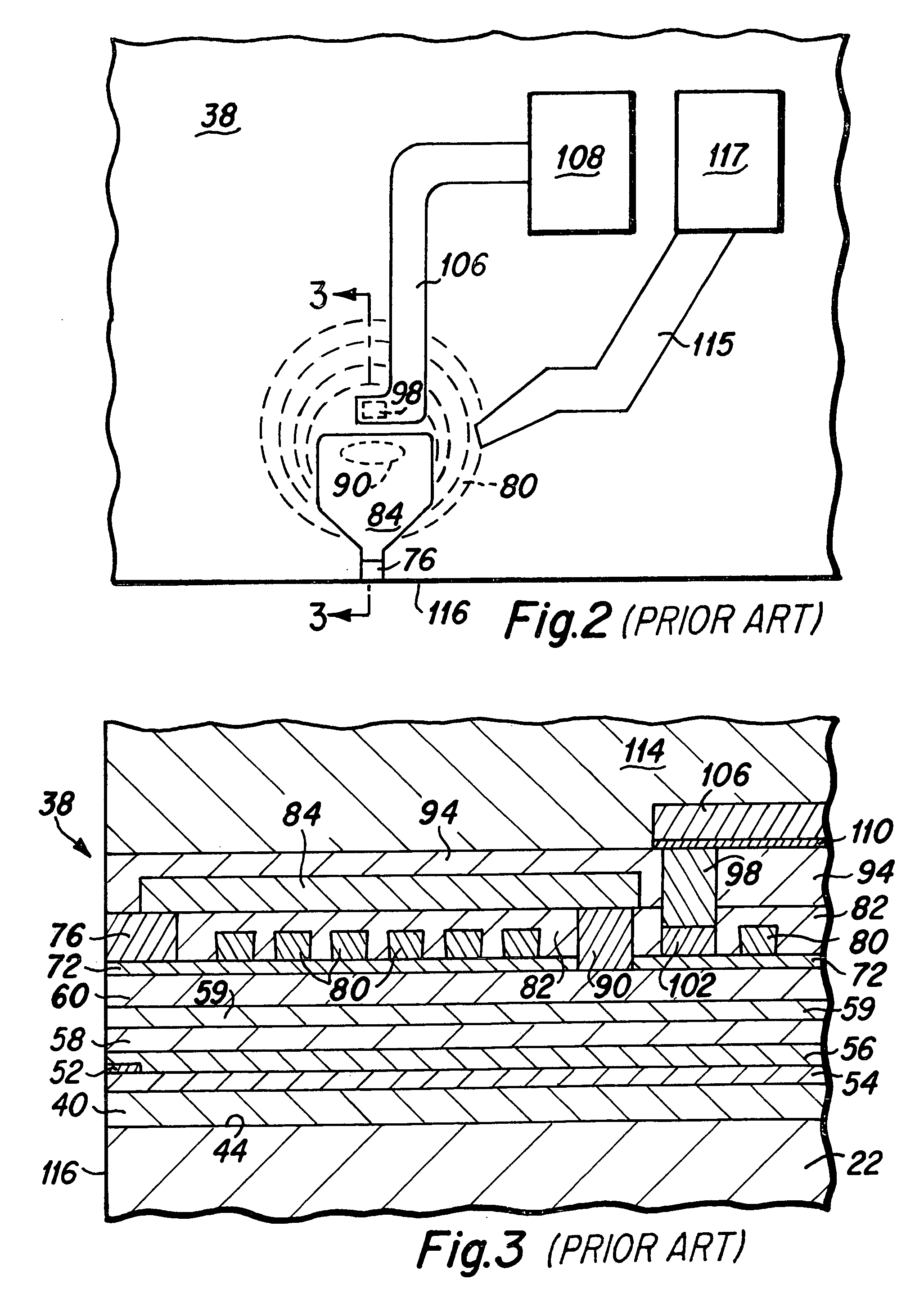
[0028]As will be understood from the following detailed description, the magnetic head of the present invention includes heat sink structures that are fabricated within the magnetic head to draw away excess heat that is generated within the induction coil and magnetic poles during the inductive write head operation. FIG. 4 is a top plan view depicting various components of a magnetic head 118 of the present invention, and FIG. 5 is a side cross-sectional view of the magnetic head depicted in FIG. 4, taken along lines 5—5 of FIG. 4. The magnetic head of the present invention, as depicted in FIGS. 4 and 5 includes many structures and components of the prior art magnetic head depicted in FIGS. 2 and 3, and similar structures are similarly numbered for ease of comprehension. Therefore, as depicted in FIGS. 4 and 5, the magnetic head of the present invention may include a first magnetic shield layer (S1) 40 that is formed on a slider body 22, a read head sensor element 52 that is dispose...

embodiment 118

[0034]A lower heat sink structure 144 is next fabricated upon the electrical insulation layer 59. The lower heat sink structure may be fabricated utilizing well known photolithographic techniques in which a seed layer 148 typically comprised of copper, is deposited, followed by the fabrication of a photoresist layer (not shown) having a heat sink trench formed therein, followed by the electroplating of the lower heat sink structure 144 that is preferably comprised of copper upon the seed layer 148 within the trench. Thereafter, the photoresist and excess seed layer are removed, and insulation material such as alumina 150 is deposited, and a chemical mechanical polishing (CMP) step is performed to create a flat upper surface to the heat sink structure 144 for the continued fabrication of further magnetic head structures. This photolithographic process for forming the lower heat sink 144 is substantially similar to the process for fabricating the electrical lead and heat sink of the m...
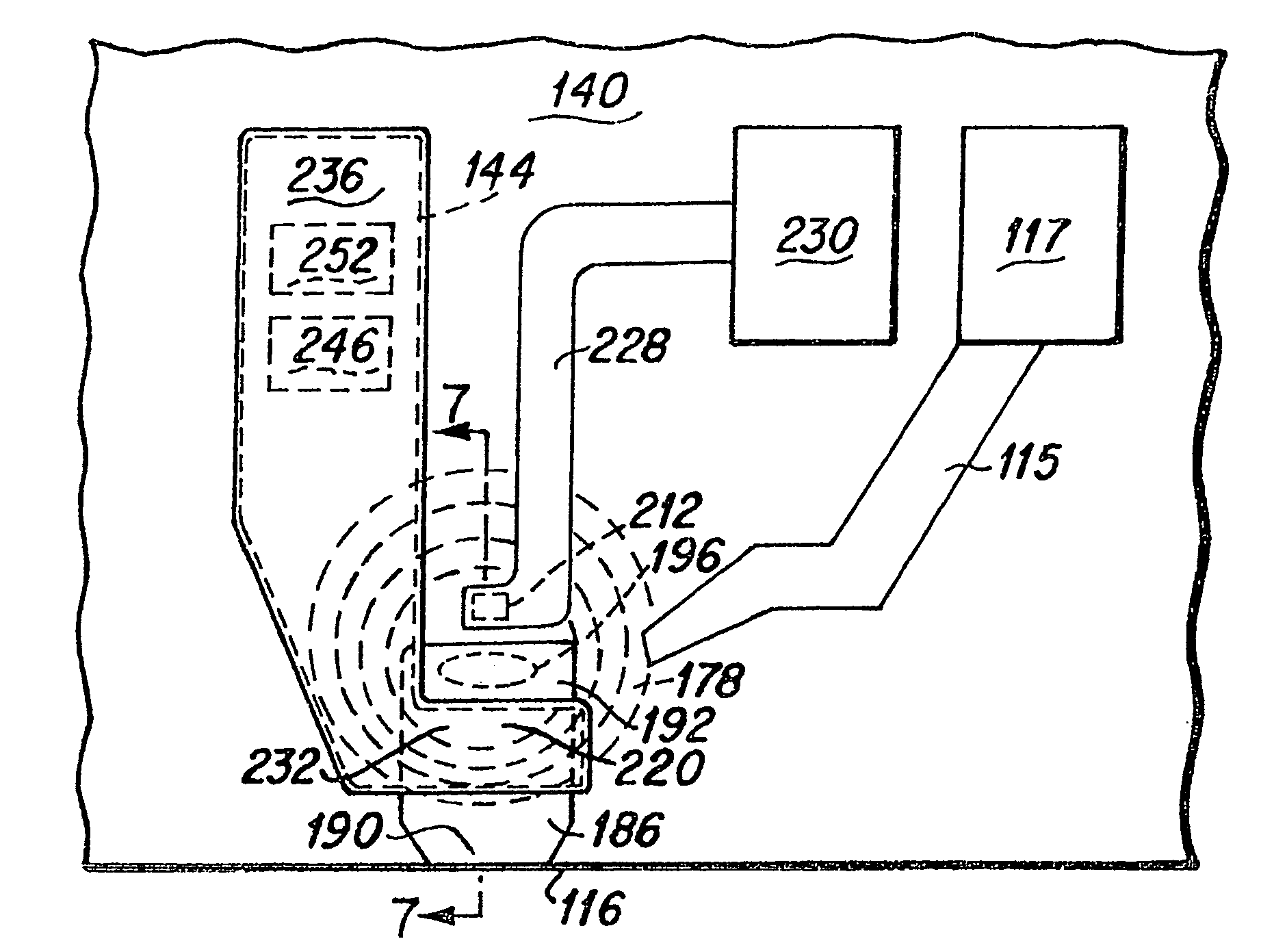
embodiment 140

[0036]As is best seen in the top view of FIG. 6, the upper heat sink 220 is preferably formed with a first enlarged portion 232 that is disposed above the yoke 192 and which is interconnected to a second substantial portion 236 that is disposed away from the critical components of the head 140. The lower heat sink 144 may be formed with a shape that is similar to the shape of the upper heat sink 220. The two heat sinks 144 and 220 of the magnetic head embodiment 140 serve to provide enhanced heat dissipation from the inductive write head and provide thermal protection to the read sensor 52 and pole tip 160 structures of the magnetic head 140.

[0037]In an enhanced embodiment of the magnetic head 140, as is best seen in FIG. 6, a heat sink interconnect via (not shown) may be fabricated through insulation layers that have been deposited down to the lower heat sink structure 144. This heat sink interconnect via may be fabricated in the same via formation step in which the electrical inte...


PUM

PropertyMeasurementUnit
magneticaaaaaaaaaa
thicknessaaaaaaaaaa
electricalaaaaaaaaaa

Abstract

A magnetic head having a heat sink structure that is disposed proximate the induction coil to draw heat away from sensitive components of the head. The heat sink is fabricated above the second magnetic pole, and is therefore fabricated subsequent to the fabrication of the more delicate components of the magnetic head. In a preferred embodiment, the heat sink is fabricated photolithographically in the same process steps in which the electrical lead to the center tap of the induction coil is fabricated. The only difference in the magnetic head fabrication process is the modification of the photolithographic mask that is used to create the electroplating trench in which the electrical lead is electroplated, and the change to the mask involves the creation of a second opening within the mask for the creation of an electroplating trench at the location of the heat sink.

Description

BACKGROUND OF THE INVENTION[0001]1. Field of the Invention[0002]The present invention relates generally to magnetic heads having inductive write head structures, and more particularly to such magnetic heads having heat sink structures formed therein for the dissipation of heat generated by the inductive write head.[0003]2. Description of the Prior Art[0004]Hard disk drives include magnetic heads that are designed to write data onto narrow data tracks upon the data disk of the disk drive, and to read data from the narrow data tracks. The ongoing effort to increase the areal data storage density of the hard disk drive results in the development and usage of ever smaller and increasingly delicate magnetic pole tips and magnetoresistive sensors for writing and reading increasingly smaller data bits onto the disk.[0005]As is well known, the data writing process involves the use of an induction coil to generate magnetic fields within the magnetic poles of the write head, and the electrica...

Claims


Application Information

Patent Timeline
Patent Type & Authority Patents(United States)
IPC IPC(8): G11B5/40G11B5/31G11B5/127G11B5/147
CPCG11B5/3133
Inventor LILLE, JEFFREY S.
Owner WESTERN DIGITAL TECH INC
Why Eureka
Try Eureka