High availability synchronization architecture

a synchronization architecture and high availability technology, applied in the field of high availability computer networks, can solve the problems of consuming a significant amount of time and typically complex switching in a network

Inactive Publication Date: 2007-03-20
AVAGO TECH INT SALES PTE LTD
View PDF12 Cites 81 Cited by
  • Summary
  • Abstract
  • Description
  • Claims
  • Application Information

AI Technical Summary

Benefits of technology

[0012]The fail-over process involves multiple stages of processing of various executable components of the image. Some stages may depend on the prior execution of other stages. In accordance with another aspect of the invention, once it is determined that a fail-over to the standby image is needed, the standby image pulls control away from the failed active image. The preferred fail-over process includes the use of a staging table which permits the standby image's FSS facility to efficiently schedule the various stages of the fail-over process taking into account the inter-stage dependencies noted above.
[0013]In accordance with another preferred embodiment of the invention, a standby CP which becomes the active CP, re-issues all messages that the previously active CP had issued and which have not yet completed. Each transaction of messages through the network is assigned a transaction identifier (“XID”) that uniquely distinguishes that transaction from other transactions. In accordance with a preferred embodiment, the newly active CP uses a different range of XIDs than its predecessor CP. By using a different range of XID values, the newly active CP can determine whether an incoming response message is responsive to a message that originated from the previously active CP or the newly activated CP. The currently active CP preferably ignores all response messages that do not have an XID in the CP's XID range. This ensures proper and reliable messaging in the network during a fail-over event.

Problems solved by technology

The switches in a network typically are relatively complex devices that include microprocessors, memory, and related components and execute firmware stored in non-volatile memory such as read only memory (“ROM”).
This fail-over process involves the coordination of a great deal of software state and hardware configuration information and, accordingly, consumes a significant amount of time.

Method used


Image

  • High availability synchronization architecture
  • High availability synchronization architecture
  • High availability synchronization architecture

Examples


Embodiment Construction

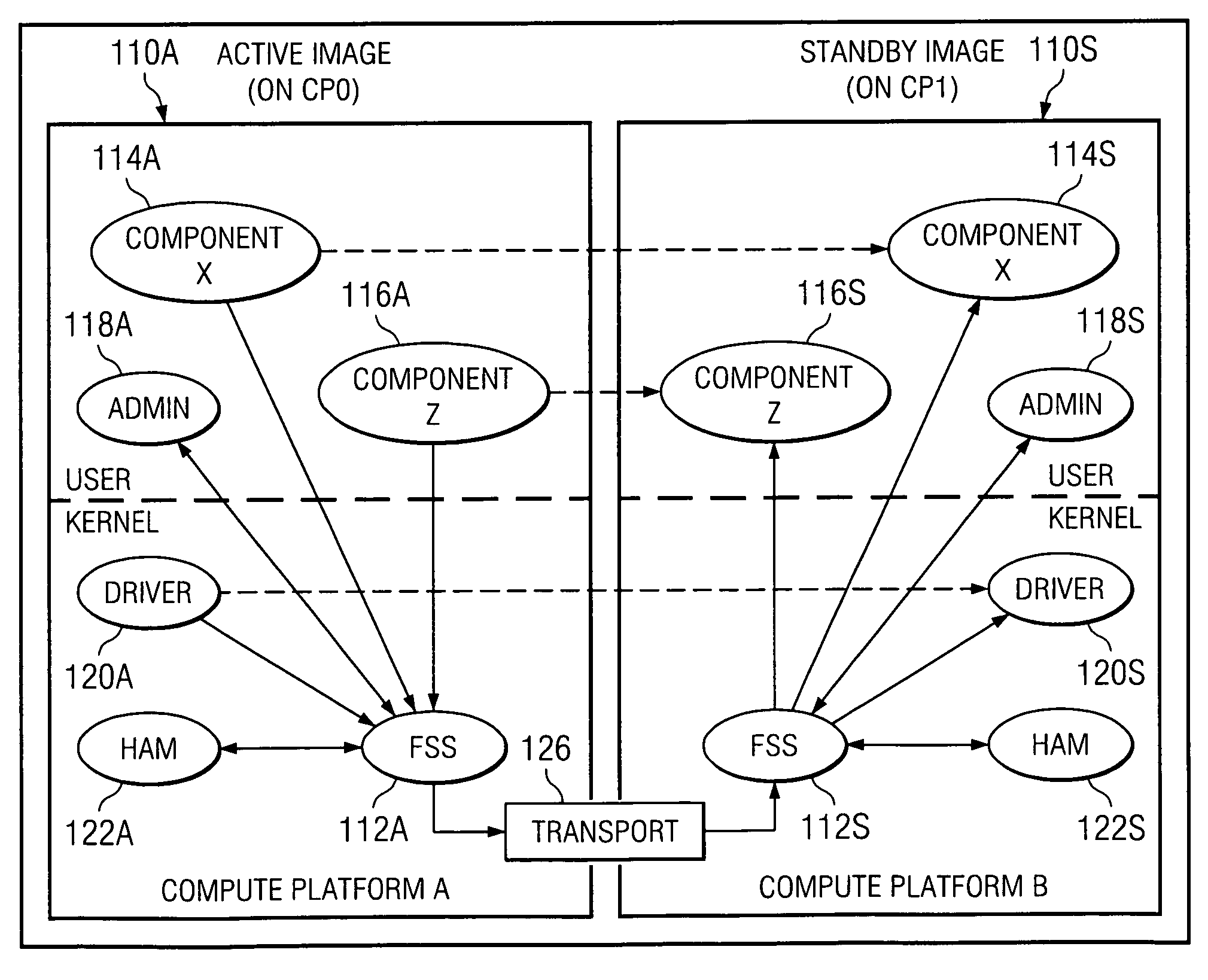
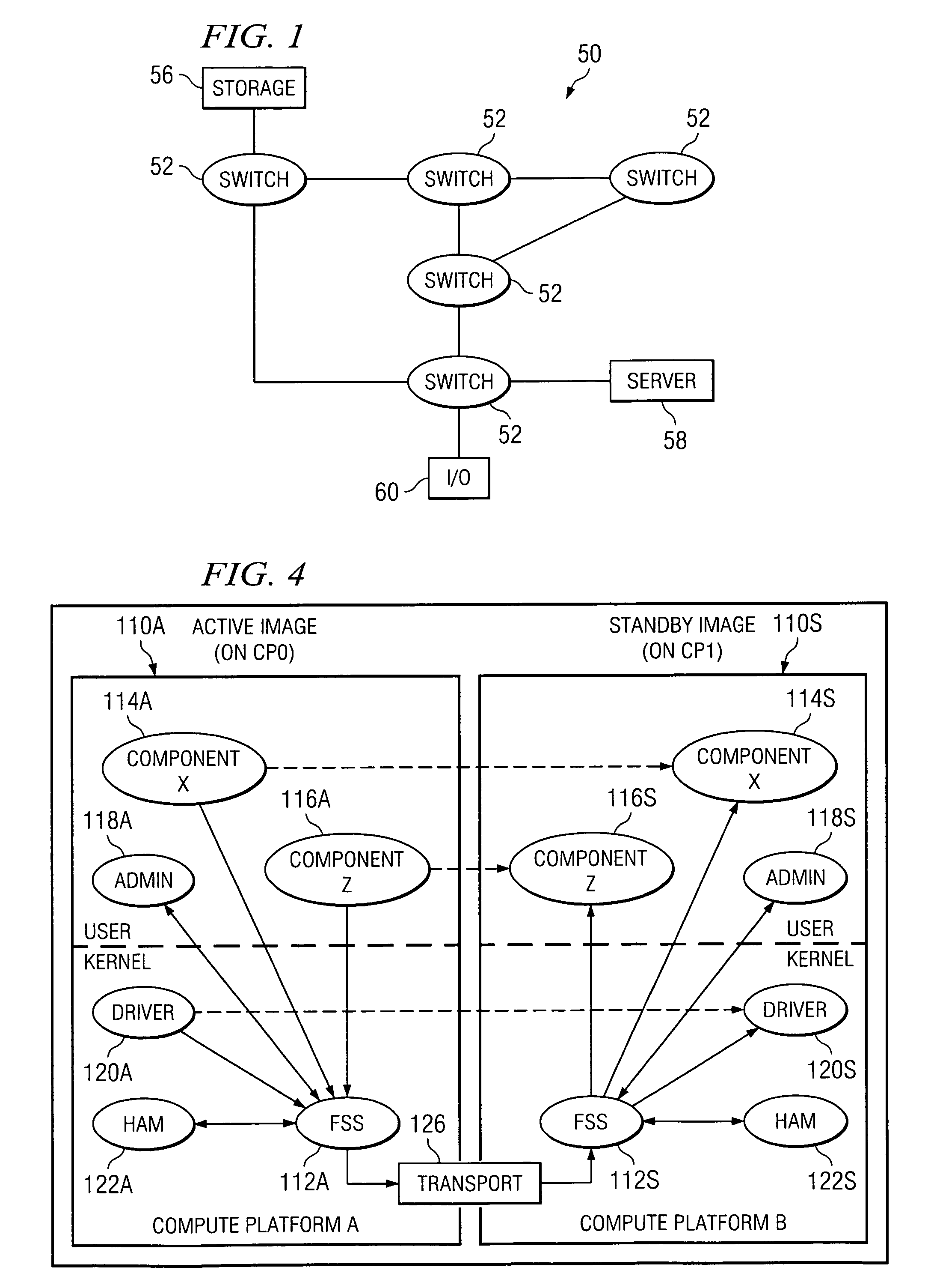
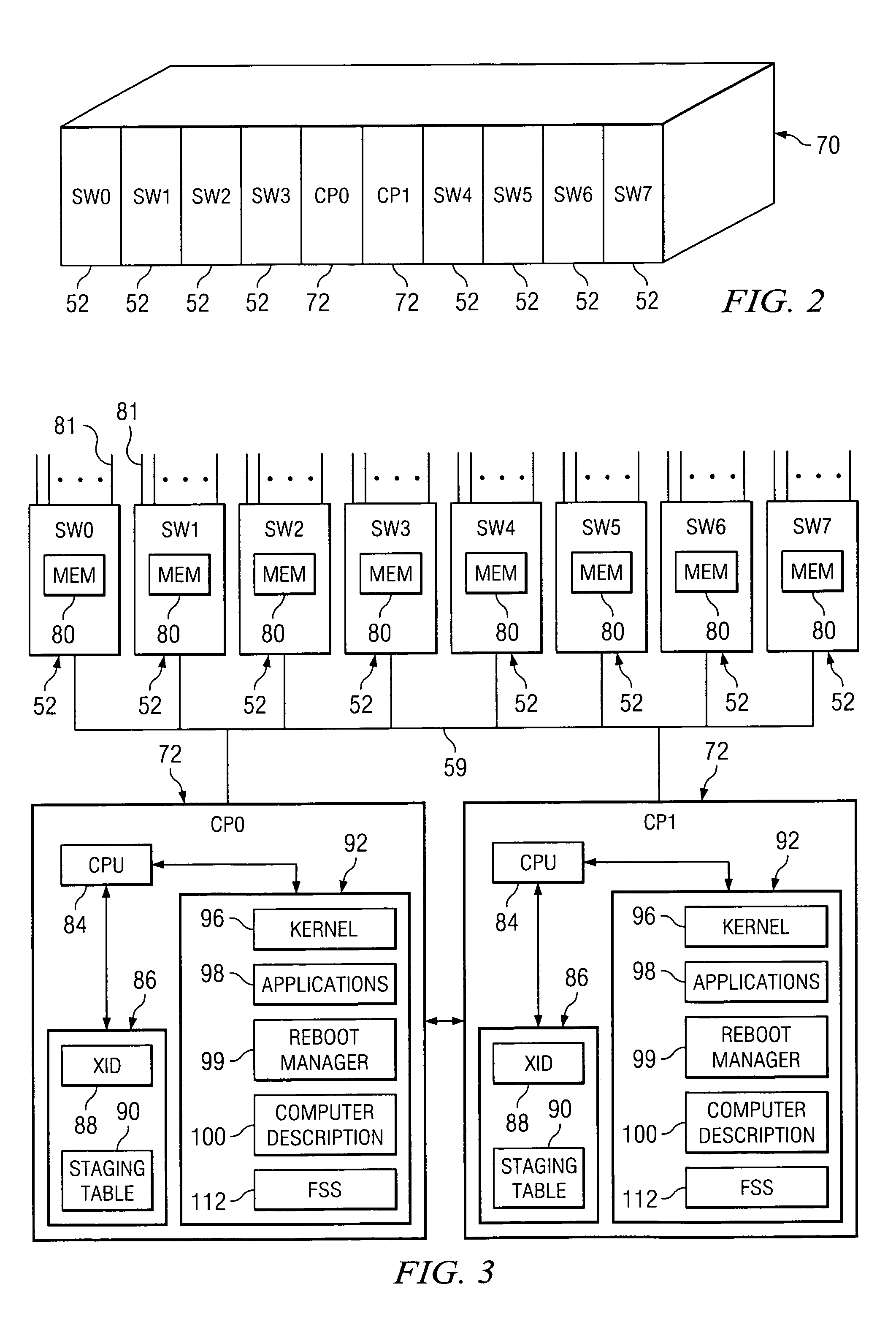
[0010]The preferred embodiments of the present invention solve the problems noted above by a “high availability” system which comprises one or more switches (or other electronic devices) under the control of one or more control processors (“CPs”). One of the CPs is deemed to be the “active” CP, while the other CP is kept in a “standby” mode. Each CP generally has the same software load including a fabric state synchronization (“FSS”) facility. The FSSs of each CP communicate with each other.

[0011]In accordance with a preferred embodiment of the invention, the state information pertaining to the active “image” (i.e., the software service running on the active CP) is continuously provided to a standby copy of the image (the “standby image”). The FSSs perform the function of synchronizing the standby image to the active image. The state information generally includes configuration and operational dynamically changing parameters and other information regarding the active image. By keepi...


PUM


Abstract

A “high availability” system comprises one or more switches under the control of multiple control processors (“CPs”). One of the CPs is deemed to be “active,” while the other CP is kept in a “standby” mode. Each CP generally has the same software load including a fabric state synchronization (“FSS”) facility. The FSSs of each CP communicate with each other. The state information pertaining to an active “image” is continuously provided to a standby copy of the image (“standby image”). The CPs' FSSs perform the function of synchronizing the standby image to the active image. The state information generally includes configuration and operational parameters and other information regarding the active image. By keeping the standby image synchronized to the active image, the standby image can be rapidly transitioned to the active mode if the active image experiences a fault and continue where the previous active image left off.

Description

CROSS-REFERENCE TO RELATED APPLICATIONS[0001]Not applicable.Statement Regarding Federally Sponsored Research or Development[0002]Not applicable.BACKGROUND OF THE INVENTION[0003]1. Field of the Invention[0004]The present invention generally relates to high availability computer networks. More particularly, the invention relates to a synchronization technique used to synchronize a standby software image to an active image to permit rapid fail-over to the standby image in the event of a failure associated with the active image.[0005]2. Background Information[0006]Initially, computers were most typically used in a standalone manner. It is now commonplace for computers and other types of computer-related and electronic devices to communicate with each other over a network. The ability for computers to communicate with one another has lead to the creation of networks ranging from small networks comprising two or three computers to vast networks comprising hundreds or even thousands of com...

Claims


Application Information

Patent Timeline
Patent Type & Authority Patents(United States)
IPC IPC(8): G06F11/00G06F15/00H04L69/40
CPCG06F11/2023G06F11/2038G06F11/2097H04L67/1095H04L69/40H04L29/06H04L69/329H04L9/40
Inventor ZHOU, BILL J.HAMMONS, RICHARD L.
Owner AVAGO TECH INT SALES PTE LTD
Why Eureka
Try Eureka