Systems and methods for enhancing performance of a coprocessor
Inactive Publication Date: 2008-09-02
MICROSOFT TECH LICENSING LLC
View PDF35 Cites 52 Cited by
Summary
Abstract
Description
Claims
Application Information
AI Technical Summary
This helps you quickly interpret patents by identifying the three key elements:
Problems solved by technology
Method used
Benefits of technology
[0008]This invention provides various techniques, that can be used in tandem or individually, for minimizing coprocessor “starvation,” and for effectively scheduling the processing in a coprocessor for greater efficiency and power. In this regard, a run list is provided by a Central Processing unit (“CPU”) allowing a coprocessor to switch immediately, on the occurrence of a switching event such as a page fault or task completion, from one task to the next, without waiting for CPU intervention. In addition to the run list, a method called “surface faulting” allows a coprocessor to fault at the beginning of a large task, such as rendering a surface, rather than somewhere in the middle of the surface after significant processi
Problems solved by technology
While current computer systems and coprocessors perform adequately when running a single graphically intensive application, they may experience problems when running multiple graphically intensive applications.
One reason for this is the typical coprocessor's inability to efficiently schedule its workload.
While this has not been a significant concern when running a single graphically intensive program, the problem of hogging the coprocessor can become more serious when multiple applications attempt to use a coprocessor.
While the problem of apportioning processing be
Method used
Image
Click on the blue label to locate the original text in one second.
Reading with bidirectional positioning of images and text.
Examples
Embodiment Construction
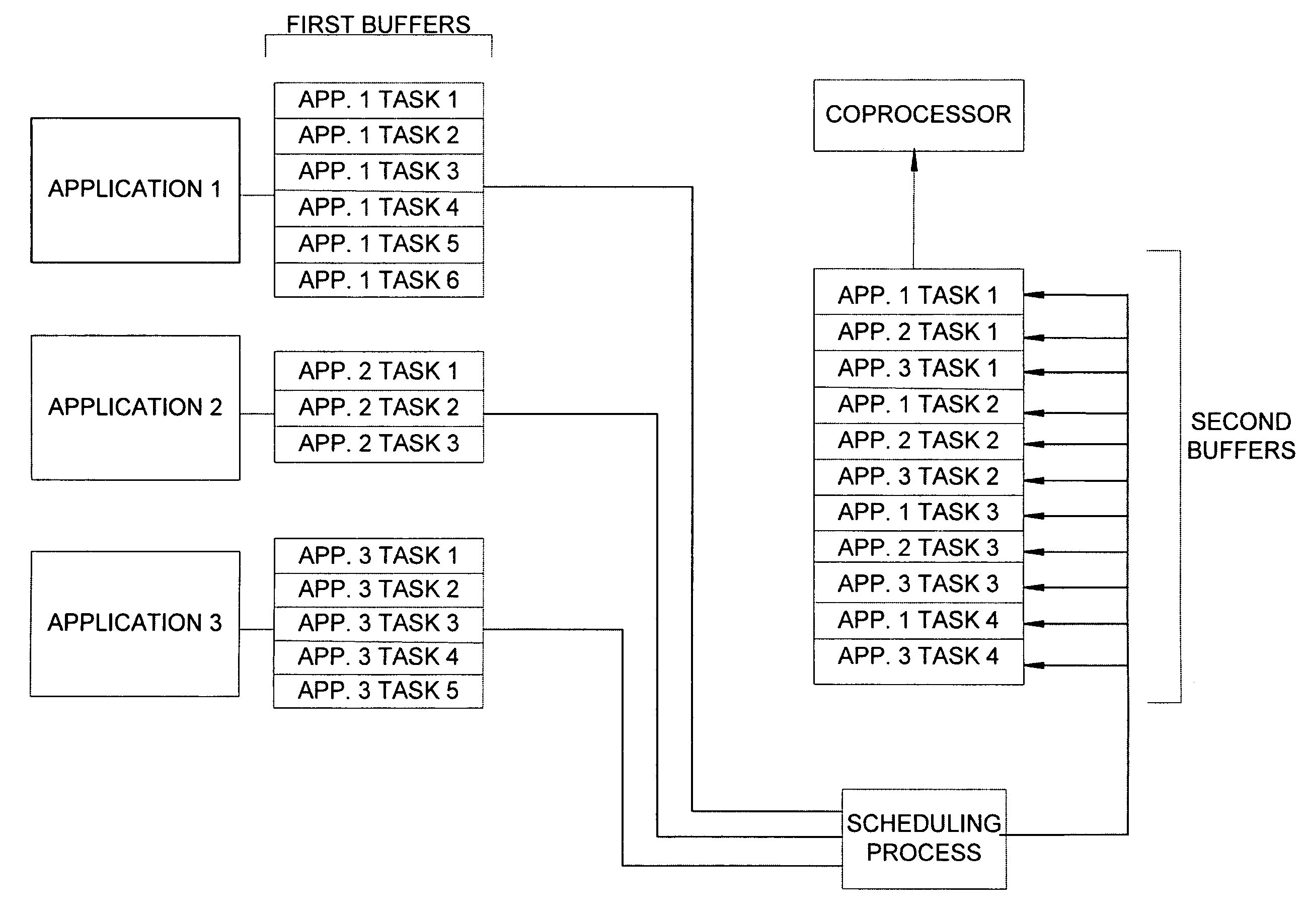
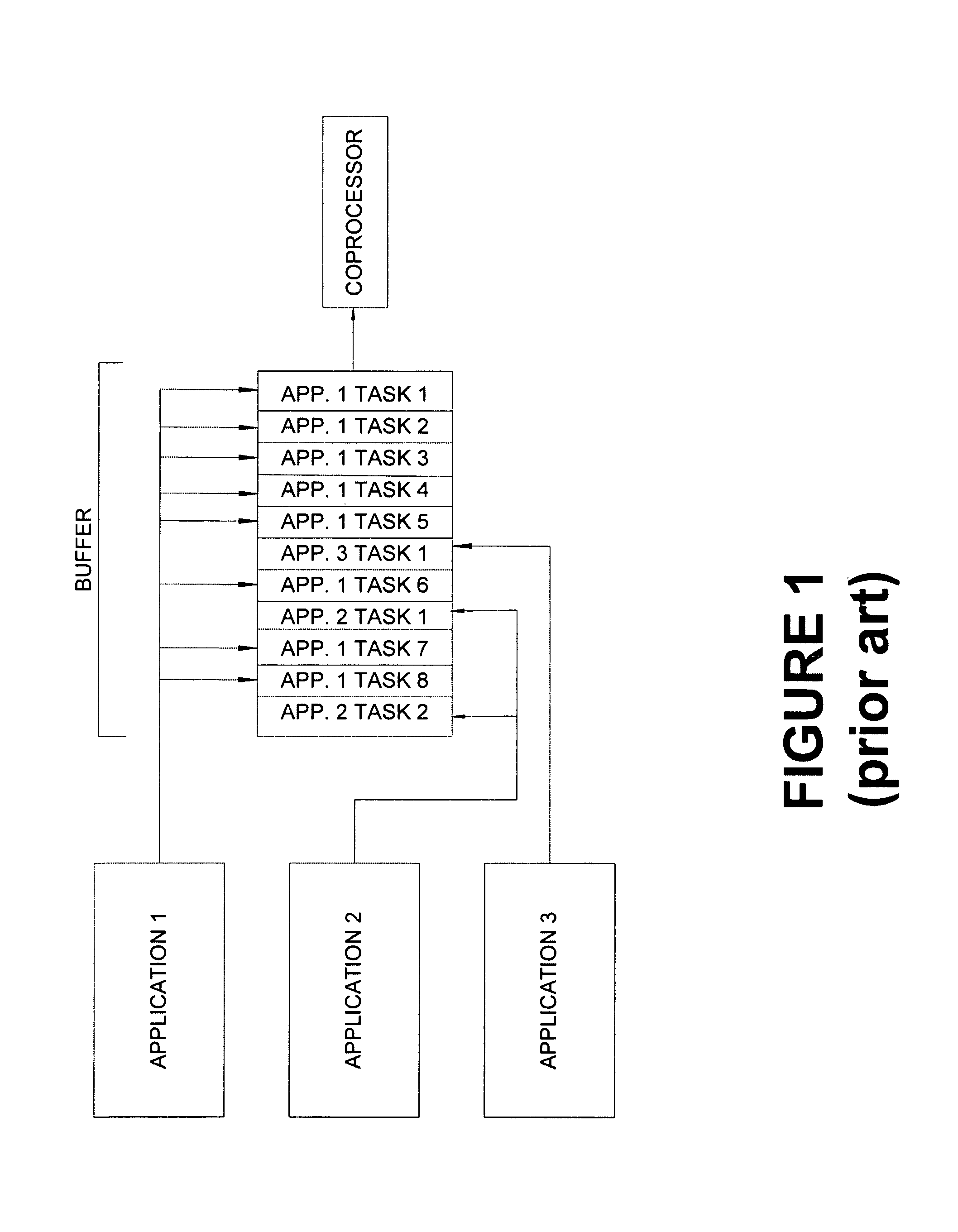
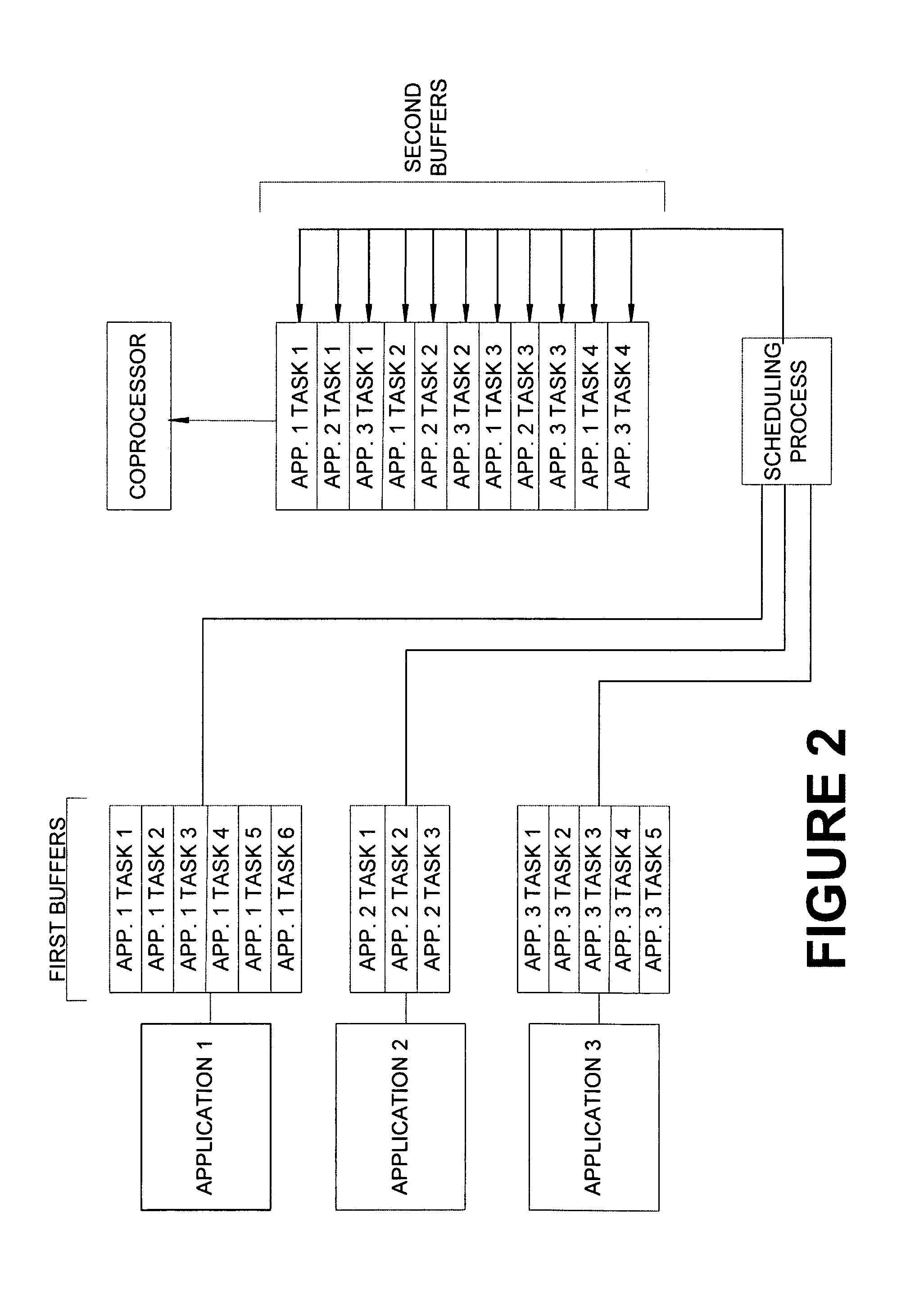
[0036]Several of the improvements accomplished by the present invention can be conceptually illustrated through a comparison of FIG. 1 and FIG. 2. FIG. 1 represents a typical prior art approach to task scheduling for a coprocessor. A buffer is provided which can be accessed by various applications, e.g., Application 1, Application 2, and Application 3. The applications can load tasks for the coprocessor into a buffer, and those tasks can be processed by the coprocessor after previously submitted tasks are completed. As illustrated, this approach leaves open a potential “hogging” of the coprocessor. In FIG. 1, App. 1 is hogging the coprocessor. App. 1 has requested that the coprocessor work on eight tasks, while the other two applications combined have requested work on only three tasks. In situations like these where multiple applications need the coprocessor, a system such as that provided by FIG. 2 may provide improved functionality.
[0037]FIG. 2 illustrates a system and method, in...
PUM
Abstract
Techniques for minimizing coprocessor “starvation,” and for effectively scheduling processing in a coprocessor for greater efficiency and power. A run list is provided allowing a coprocessor to switch from one task to the next, without waiting for CPU intervention. A method called “surface faulting” allows a coprocessor to fault at the beginning of a large task rather than somewhere in the middle of the task. DMA control instructions, namely a “fence,” a “trap” and a “enable/disable context switching,” can be inserted into a processing stream to cause a coprocessor to perform tasks that enhance coprocessor efficiency and power. These instructions can also be used to build high-level synchronization objects. Finally, a “flip” technique is described that can switch a base reference for a display from one location to another, thereby changing the entire display surface.
Description
CROSS-REFERENCE TO RELATED APPLICATION[0001]This application claims the benefit of U.S. Provisional Application No. 60 / 448,402, filed Feb. 18, 2003, entitled “GPU Scheduler Overview;” U.S. Provisional Application No. 60 / 448,399, filed Feb. 18, 2003, entitled “Video Memory Management Architecture Specification;” U.S. Provisional Application No. 60 / 448,440, filed Feb. 18, 2003, entitled “Video Memory Management Rectangular Heap;” and U.S. Provisional Application No. 60 / 474,513, filed May 29, 2003, entitled “Multithreaded Kernel for GPU.”[0002]This application is related to co-pending U.S. application Ser. No. 10 / 763,777, filed on Jan. 22, 2004, entitled “Multithreaded Kernel for Graphics Processing Unit.”FIELD OF THE INVENTION[0003]The present invention relates to computer processors, and more particularly to hardware and software for scheduling processing of coprocessors.BACKGROUND OF THE INVENTION[0004]Many computer systems now include coprocessors, for example, graphics processing ...
Claims
Application Information
Patent Timeline
Application Date:The date an application was filed.
Publication Date:The date a patent or application was officially published.
First Publication Date:The earliest publication date of a patent with the same application number.
Issue Date:Publication date of the patent grant document.
PCT Entry Date:The Entry date of PCT National Phase.
Estimated Expiry Date:The statutory expiry date of a patent right according to the Patent Law, and it is the longest term of protection that the patent right can achieve without the termination of the patent right due to other reasons(Term extension factor has been taken into account ).
Invalid Date:Actual expiry date is based on effective date or publication date of legal transaction data of invalid patent.