Pocket mattress with varying height

a pocket mattress and height technology, applied in the field of spring mattresses, can solve the problems of relatively simple and cost-effective manufacturing of mattresses, and achieve the effects of flexible and efficient production, simple and cost-effective production equipment, and cost-effective production

Active Publication Date: 2007-03-27
STJERNFJADRAR
View PDF8 Cites 68 Cited by
  • Summary
  • Abstract
  • Description
  • Claims
  • Application Information

AI Technical Summary

Benefits of technology

[0010]By means of the invention, there is provided a variation in height among the spring units within each string, in addition to a possible further variation between the strings. In this way, variations of the properties of the mattress across the mattress surface can be provided in a simple way. For example, it is possible to arrange lower and higher spring units in patterns, making the mattress obtain a softer surface layer and a more rigid lower layer. It is also possible to easily provide different zones of the mattress, such as zones with differently soft or differently thick surface layers, or zones with and without such surface layers.
[0026]The means for arranging coil springs as spring units in individual covering pockets successively in elongate strings preferably comprises means for folding a covering material in the longitudinal direction of the string; first welding equipment for arranging welds in the transverse direction for partitioning off covering pockets; insertion means for inserting springs into the covering pockets; and second welding equipment for arranging a weld in the longitudinal direction of the string to seal the opening of the covering pockets. Moreover the means for varying the height of at least one spring unit within at least one string relative to the height of the other spring units within the same string preferably comprises means for arranging at least one additional weld in the longitudinal direction in said covering pocket. This offers relatively simple and cost-effective production equipment while at the same time flexible and efficient production can be obtained.

Problems solved by technology

At the same time the mattress can be manufactured in a relatively uncomplicated and cost-effective manner.

Method used


Image

  • Pocket mattress with varying height
  • Pocket mattress with varying height
  • Pocket mattress with varying height

Examples


first embodiment

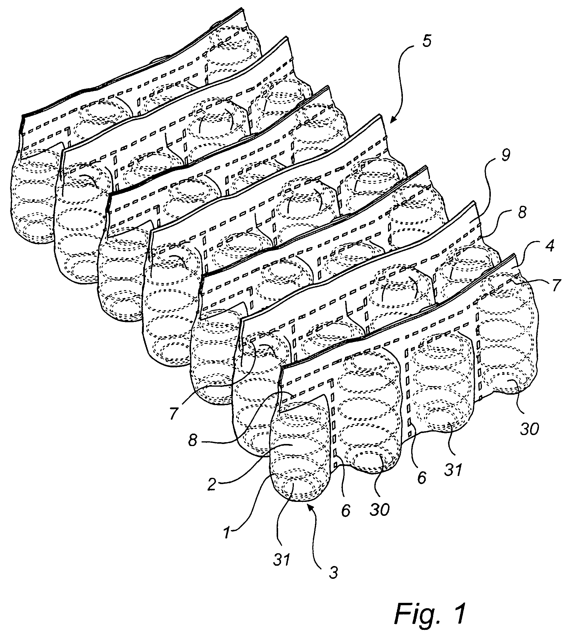
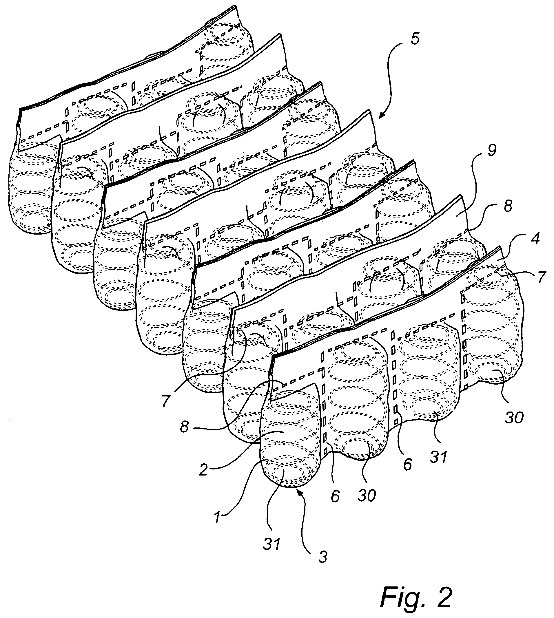
[0048]The spring units 30, 31 with different heights can advantageously be distributed over the surface of the mattress. In the first embodiment, shown in FIGS. 1, 3 and 5, the number of low spring units 31 is essentially the same as the number of high spring units 30, i.e. the ratio of the number of units in the group with the smallest number of units to the number of units in the group with the largest number of units is essentially 1. The spring units with a deviating height, i.e. the low spring units 31, are further arranged in a regular and repetitive pattern, where every second spring unit in the strings is high and every second is low. The strings are further offset relative to each other, so that also in a direction transversely of the longitudinal direction of the strings there are alternately high and low spring units. As a result, the spring units with the respective heights form diagonal lines across the surface of the mattress. This pattern is most clearly to be seen in...

second embodiment

[0049]In a second embodiment shown in FIG. 6, the number of low spring units 31 is essentially the same as the number of high spring units 30. The spring units are also in this case arranged in a regular and repetitive pattern, but here the spring units with the respective heights are arranged in pairs. Moreover the strings are offset relative to each other, but each string is offset by two spring positions.

[0050]Also in a second embodiment, shown in FIG. 7, the number of low spring units 31 is essentially the same as the number of high spring units 30. Also in this case, the spring units are arranged in a regular and repetitive pattern, but here the spring units with the respective heights are arranged in pairs. The strings are offset relative to each other so that also in a direction transversely of the longitudinal direction of the strings alternately high and low spring units are arranged in pairs. The spring units form groups of spring units with different heights, which togeth...

third embodiment

[0051]In a third embodiment, shown in FIG. 8, the number of low spring units 31 is essentially the same as the number of high spring units 30. The spring units are also in this case arranged in a regular and repetitive pattern, and the spring units with the respective heights are arranged in pairs within each string. The strings are further offset relative to each other so that also in a direction transversely of the longitudinal direction of the strings, alternately high and low spring units are arranged in pairs, but in contrast to the embodiment in FIG. 6, the displacement here corresponds to one spring unit only, not two. The spring units form diagonal zigzag lines across the surface of the mattress.


PUM


Abstract

A mattress comprising coil springs arranged as spring units in covering pockets, a so-called pocket mattress, is provided. The spring units of the mattress are arranged in succession in elongate strings, the mattress comprising a plurality of such interconnected strings arranged side by side. A distinguishing feature of the mattress is that at least one spring unit within at least one string has a height that differs from the height of the other spring units within the same string. A method and a device for manufacturing such a mattress are also provided.

Description

FIELD OF THE INVENTION[0001]The present invention relates to a spring mattress comprising springs enclosed in coverings, a so-called pocket mattress, as well as a method and a device for manufacturing such a mattress.BACKGROUND ART[0002]A common technique for manufacturing spring mattresses is the “pocket technique”. This means that the springs are enclosed in pockets, so-called covering pockets, i.e. they are individually enclosed by a covering material. In this way, the springs become relatively individually flexible, so that each spring may flex separately without affecting the neighbouring springs, thus increasing the user's comfort since his weight will be distributed more evenly over the surface receiving the load.[0003]It also known from, inter alia, WO 00 / 00065, EP 1048248 and U.S. Pat. No. 5,222,264 to arrange alternately in a mattress spring units-with different properties by, for instance, arranging different units in different zones of the mattress which thus-will obtain...

Claims


Application Information

Patent Timeline
Patent Type & Authority Patents(United States)
IPC IPC(8): A47C27/04A47C27/06B68G9/00
CPCA47C27/062B68G9/00A47C27/064
Inventor EDLING, KENNETHJOHANSSON, MIKAEL
Owner STJERNFJADRAR
Why Eureka
Try Eureka