Propulsion from combustion of solid propellant pellet-projectiles

a technology of solid propellant and pellets, which is applied in the direction of ram jet engines, machines/engines, gas turbine plants, etc., can solve the problems of enclosing solid charges, difficult thrust control, reuse of solid motor cases and other parts, etc., and achieves low maintenance costs, high volumetric loading of propellants, and the ability to throttle

Inactive Publication Date: 2007-03-27
KRISHNAN VINU B
View PDF12 Cites 35 Cited by
  • Summary
  • Abstract
  • Description
  • Claims
  • Application Information

AI Technical Summary

Benefits of technology

[0012]The sixth objective of the present invention is to provide a method and system for providing propulsion from combustion of solid propellant pellet-projectiles having advantages over liquid propellant engines such as but not limited to higher volumetric loading of propellants and ability to throttle.
[0013]The seventh objective of the present invention is to provide a method and system for providing pro

Problems solved by technology

A main problem with conventional solid propulsion systems are the difficulties in thrust control.
Another problem with conventional solid propulsion systems are complications involved in the reuse of solid motor case and other parts.
Another problem with conventional solid propulsion systems is that the chamber enclosing the solid charge must be strong enough to withstand the heat and high pressures of combustion.
A problem with liquid propulsion rocket engines is that they contain volatile, toxic, corrosive and/or cryogenic propellants.
Hence the engine is usually filled a short t

Method used


Image

  • Propulsion from combustion of solid propellant pellet-projectiles
  • Propulsion from combustion of solid propellant pellet-projectiles
  • Propulsion from combustion of solid propellant pellet-projectiles

Examples


Embodiment Construction

[0036]Before explaining the disclosed embodiments of the present invention in detail it is to be understood that the invention is not limited in its applications to the details of the particular arrangements shown since the invention is capable of other embodiments. Also, the terminology used herein is for the purpose of description and not of limitation.

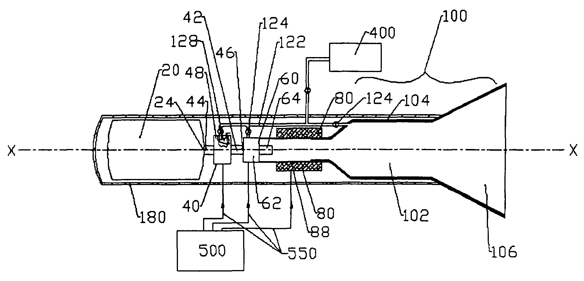
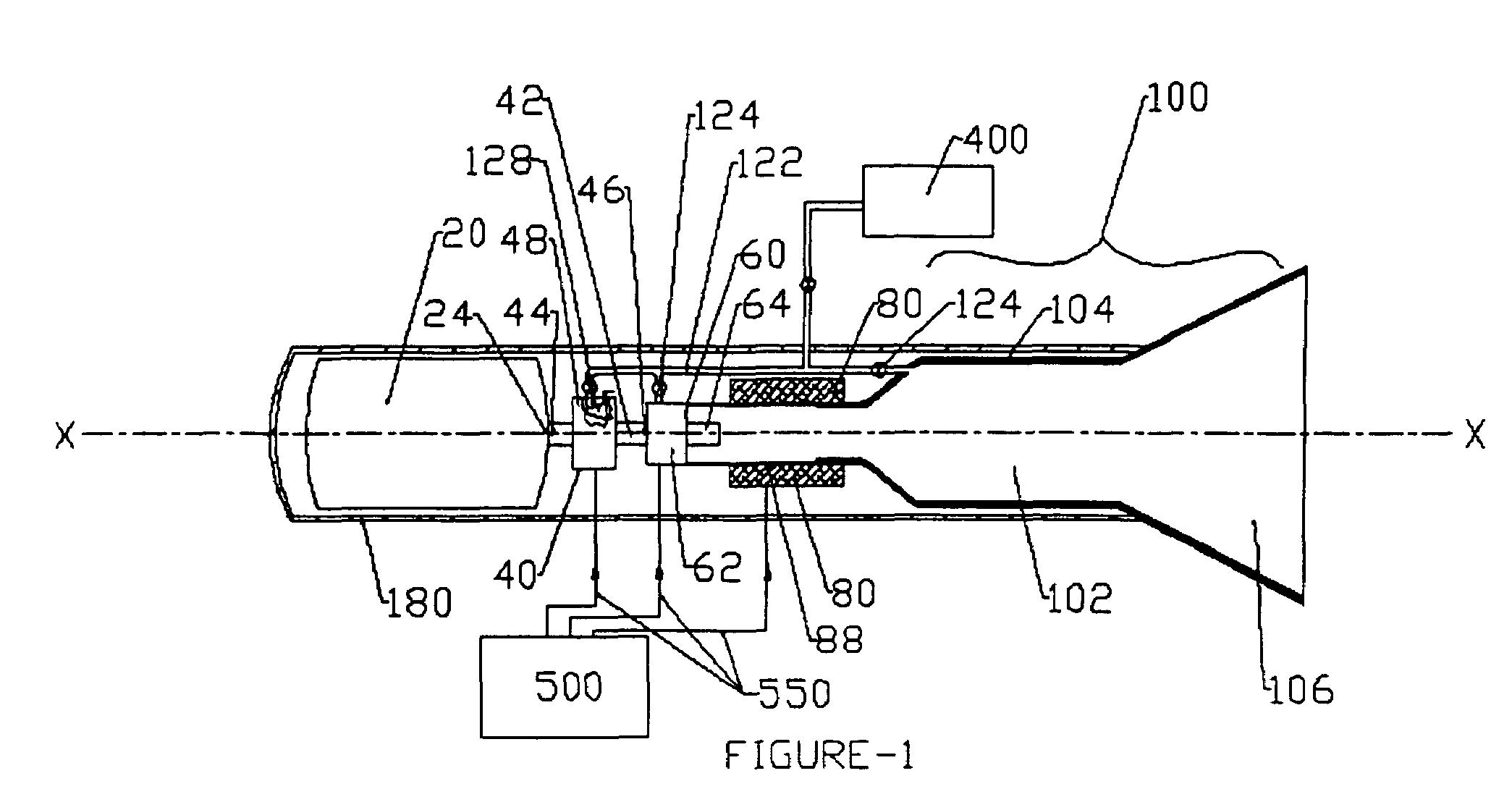
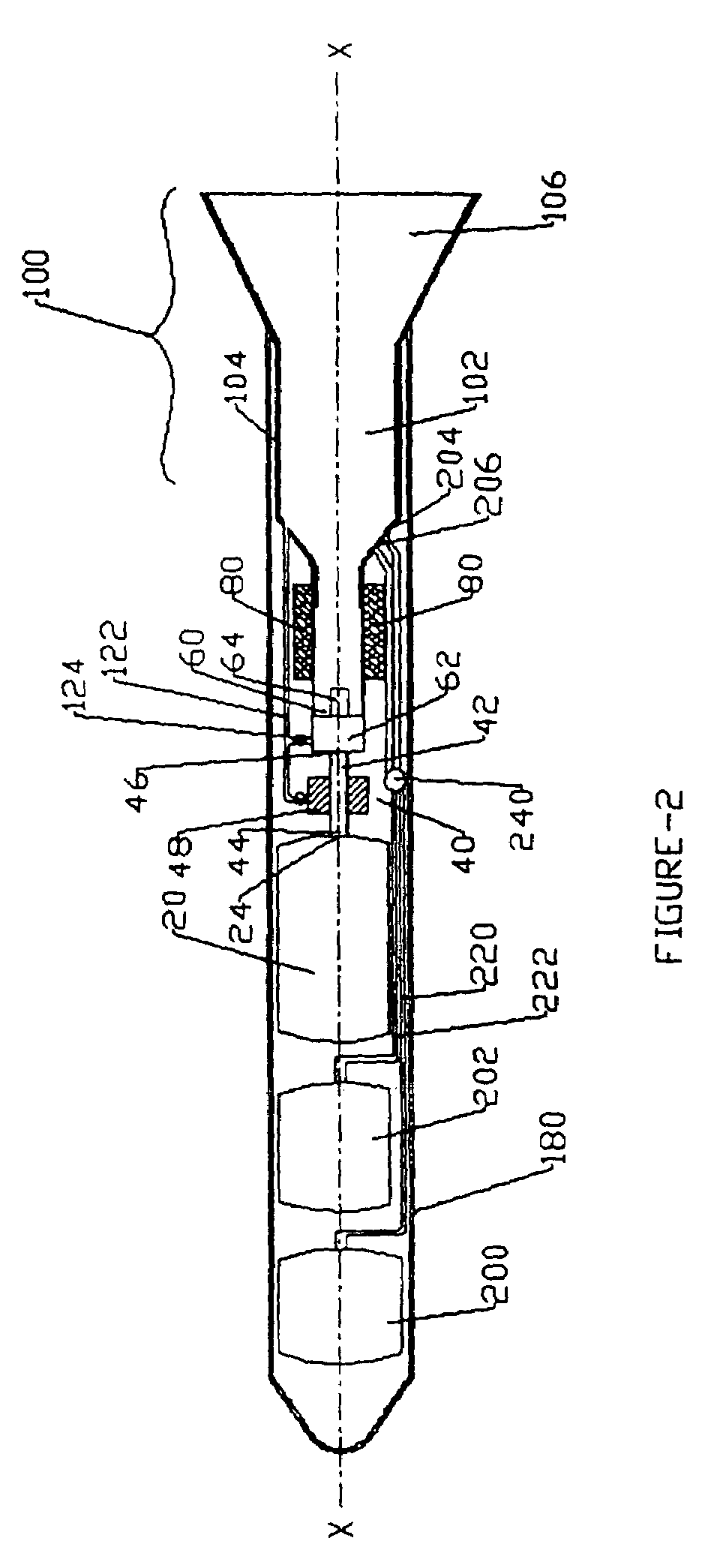
[0037]Turning now descriptively to the drawings, in which similar reference characters denote similar elements throughout the several views, the attached figures illustrate a propulsion from combustion of solid propellant pellet-projectiles, which can include a storage chamber where solid propellant pellets are stored, a feeding system having a pellet feeding channel and a pellet feeding mechanism with one end of the said channel connected to the storage chamber and other end to a gun assembly, a gun assembly positioned along a longitudinal axis to eject the pellets in the direction of said longitudinal axis at a certain velocity, a...


PUM


Abstract

Propulsion from combustion of solid propellant pellet-projectiles for providing a useful propulsion that has the advantages of both solid and liquid propulsion engines, and also can make use of either solid chemical propellants or fissionable nuclear material as the fuel. Preferred methods and systems can include a storage chamber for storing solid propellant pellets, a feeding system having a pellet feeding channel and a pellet feeding mechanism connected to the storage chamber and to a gun assembly, which is positioned along a longitudinal axis to eject the pellets at a certain velocity. A triggering system positioned between gun assembly and thrust chamber can initiate the propellant pellet-projectile, and a thrust chamber having a combustion chamber for combustion of propellant pellet-projectile with an exhaust nozzle. Additionally, an auxiliary power system can be used to power the components and various electrical and electronic systems that may be present in the invention for controlling the engine components. The gun assembly may include an ejector mechanism for ejecting the propellant pellets through at least one barrel. The triggering system can produce a medium creating an ambience for the initiation of propellant pellet-projectiles. Methods and systems can be used for space and rocket crafts, turbojets and ramjets.

Description

[0001]This invention claims the benefit of priority to U.S. Provisional Patent Application 60 / 347,451 filed Nov. 1, 2001, and 60 / 333,300 filed Nov. 14, 2001, and this invention relates generally to propulsion systems and more specifically it relates to methods and systems for the propulsion from combustion of solid propellant pellet-projectiles for providing a useful propulsion method that would have the advantages of both solid and liquid propulsion engines, and also can make use of either solid chemical propellants or fissionable nuclear material as the fuel.BACKGROUND AND PRIOR ART[0002]Propulsion systems have been in use for years. See U.S. Pat. No. 5,063,735 to Colgren. The typical propulsion systems can include solid propellant motors, liquid propulsion engines, jet engines, and a combination of jet engine and solid motor such as solid propellant gas generator to start a jet engine and Rocket-powered ducted fan engine.[0003]A main problem with conventional solid propulsion sys...

Claims


Application Information

Patent Timeline
IPC IPC(8): F02K9/72
CPCF02K7/10F02K9/08F02K9/72F02K9/94F02K9/24F05D2220/34
Inventor KRISHNAN, VINU B.
Owner KRISHNAN VINU B
Why Eureka
Try Eureka