
Method and apparatus for downhole artificial lift system protection

a technology of artificial lift system and protection device, which is applied in the direction of fluid removal, earth-moving drilling, borehole/well accessories, etc., can solve the problems of shutting down production, affecting production, and affecting production efficiency,

Active Publication Date: 2007-03-27
OILFIELD EQUIP DEVMENT CENT
View PDF16 Cites 18 Cited by
  • Summary
  • Abstract
  • Description
  • Claims
  • Application Information

AI Technical Summary

Benefits of technology

"The patent describes a system that removes scale inhibitors and other chemicals from the production stream of a well. The system includes a filter that contains the treatment chemical and a pump that removes the chemical from the filter and introduces it into the production stream. The chemical can be recharged or replenished using various methods, such as downhole reservoirs or surface feeding means. The system can also include a by-pass valve to allow fluid to by-pass the filter when sand or other particulate matter blocks it. The technical effect of this system is to prevent scale buildup and other chemical issues in the production stream, which can improve the efficiency and lifespan of the well."

Problems solved by technology

The fluids often transport solids, such as sand, as well as other potentially damaging fluids and gases, from the reservoir into the production tubing and casing, and up the production tubing to the surface.
In extreme cases, the pipe or tubing can become completely obstructed, shutting down production.
In severe conditions, scale creates a significant restriction, or even a plug, in the production tubing.
Scale build-up in the artificial lift pump can lead to failure of the pump due to blocked flow passages and broken shafts.
Scale deposits are the most common and most troublesome damage problems in the oil field and can occur in both production and injection wells.
Silica scales resemble porcelain—they are very brittle, not soluble in acid, but dissolve slowly in alkali.
Although it does not seem to be common, according to field experience and published literature, it causes a significant flow / production problem when it does occur, just as all other scales adversely affect wells.
Other scales, such as barium sulfate and strontium sulfate, also cause production problems but are much harder than ZnS.
Although chemical solvents have been used on these harder scales, the results are often disappointing.
While mechanical scale removal has been used successfully on barium and strontium sulfate scales with excellent success, it had not been used on ZnS scale.
It was conceivable that the softer scale may not respond to the same process that removed harder scales.
In certain cases, scale may be an environmental or health hazard.
When held inside the complex, the ions have a limited ability to react with other ions, clays or polymers.
Due to the time that it takes for the chemicals to reach the pump, changes in chemical mix or injection rates are very slow to affect the fluids entering the pump.
If the pump intake is above the electric motor in an Electric Submersible Pump, ESP installation, the chemicals do not protect the motor or the casing below the pump intake.
Sand produced with the fluids can cause damage to pumping systems.
Abrasion resistant pumps with engineered ceramic bearings and coated flow passages have been developed to improve pump life in wells that produce sand, but sand will eventually wear out even these special sand-tolerant pumps.
Any gap or interruption in the pack coverage may permit undesirable sand or fines to enter the producing system.
This style of intake filter has been installed in numerous wells and is effective for removal of solids, but once the filter is full of sand, fluid flow through the filter is restricted and a large pressure drop occurs.
When fluid flow to the pump ceases, the pump will cavitate and eventually fail.

Method used


Image

  • Method and apparatus for downhole artificial lift system protection
  • Method and apparatus for downhole artificial lift system protection
  • Method and apparatus for downhole artificial lift system protection

Examples


Embodiment Construction

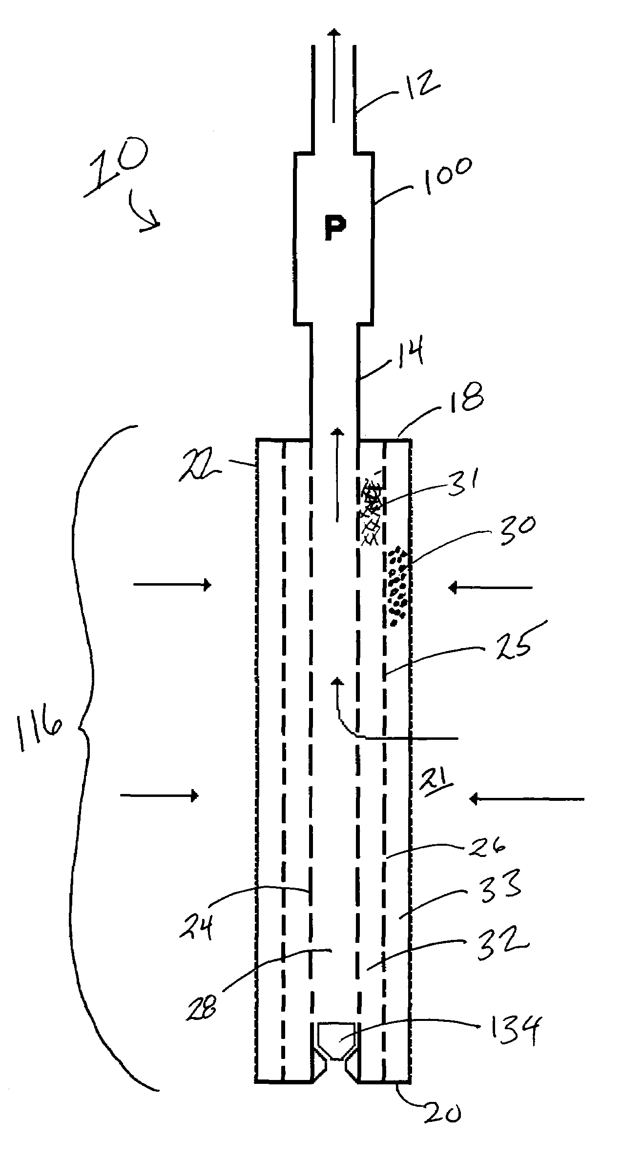
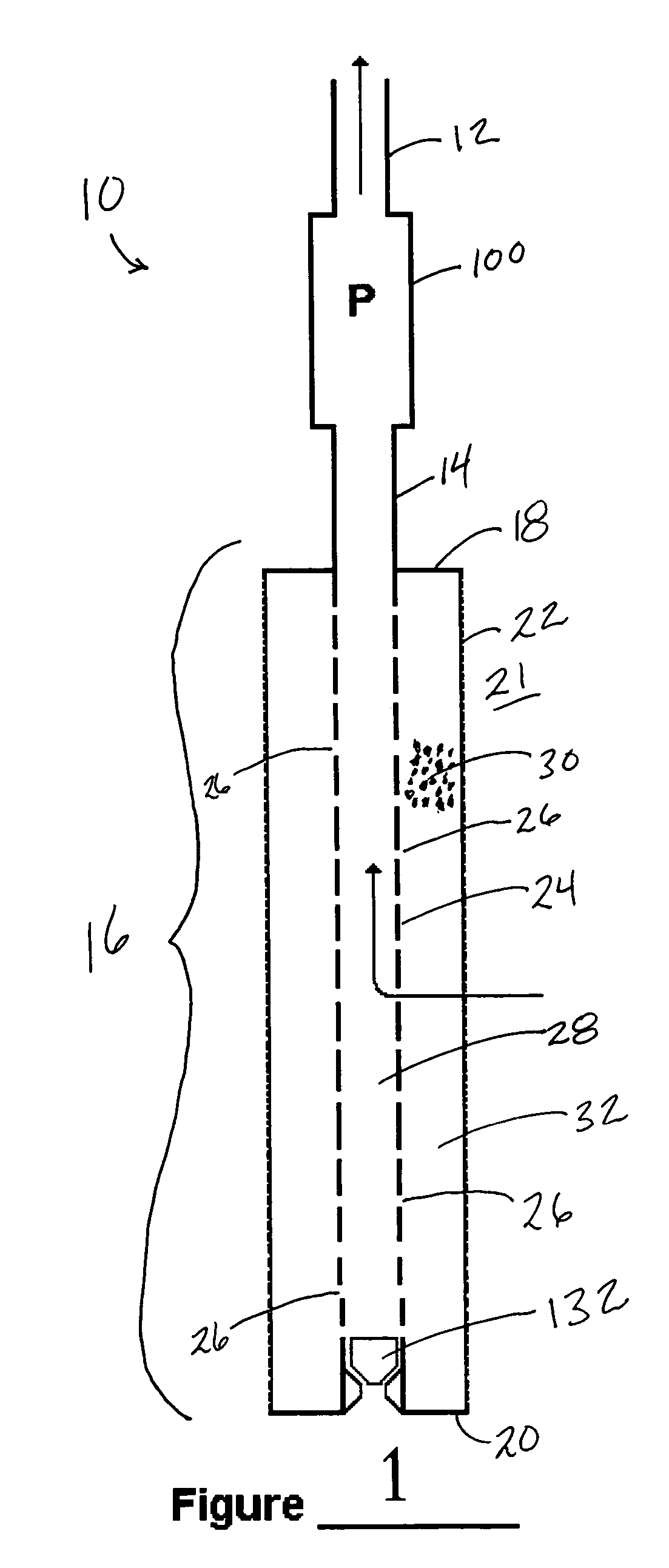
[0054]Advances in electric motor technology have made Electric Submersible Pumps (ESPs) an increasingly popular method of providing artificial lift for oil wells. Operating in the harsh conditions of the downhole environment, an ESP must be protected from ingesting corrosive, abrasive, or any other detrimental substance in the production fluids in order to provide a Mean Time Between Failure (MTBF) that justifies its use on an economic basis. In addition, treating the production fluids while downhole minimizes the potential hazards involved in bringing the production fluids to the surface while the production fluids may contain any detrimental substance. Moreover, scale build-up in production tubing and pump chambers must also be controlled in order to decrease the number of well interventions or workovers needed during the useful life of an oil well.

[0055]The present invention is a novel apparatus and method which combines the functions of preventing fines or sand from entering the...


PUM


Abstract

A fluid conditioning system designed to be installed between the well perforation and the intake of a pump used to effect artificial lift is used to filter and chemically treat production fluids. The fluid conditioning system is an apparatus that provides scale inhibitors and / or other chemical treatments into the production stream. In some embodiments, the fluid conditioning system may be a part of the production stream filter wherein the filtering material is comprised of a porous medium that contains and supports the treatment chemical. In other embodiments, the chemical treatment may be accomplished by the gradual dissolution of a solid phase chemical. The treating chemical may be recharged or replenished by various downhole reservoirs or feeding means. In yet other embodiments, the treating chemical may be replenished from the surface by means of a capillary tube. In certain other embodiments, the apparatus may be retrievable from the surface thereby permitting recharge or replenishment of the chemical in the apparatus on an as-needed basis. The filtration apparatus may incorporate a by-pass valve that allows fluid to by-pass the filter as sand or other particulate matter fills up or blocks the filter.

Description

BACKGROUND[0001]1. Field of the Invention[0002]This invention relates to oil and gas well production technology. More particularly, it relates to the in situ treatment of fluids produced by an artificial lift oil well to inhibit the formation of scale inside and outside of production tubing, pumps, valves, and the like and to reduce the amount of solids that enter the pump.[0003]2. Description of the Related Art[0004]A typical oil well produces not only oil, but also gas and water, often in significant quantity. The fluids often transport solids, such as sand, as well as other potentially damaging fluids and gases, from the reservoir into the production tubing and casing, and up the production tubing to the surface. Equipment on the surface may be used to separate these production components. The oil is recovered; the gas, depending on its composition, may be filtered, treated and piped to a collection facility or flared off; the water may be re-injected into another formation or, i...

Claims


Application Information

Patent Timeline
Patent Type & Authority Patents(United States)
IPC IPC(8): E21B43/22
CPCE21B37/06E21B43/08Y10S166/902
Inventor DELALOYE, RICHARD J.KENNEDY, STEVEN C.BODE, JEFFREYLEMBCKE, JEFFREYSMITH, KEVIN W.LUSCOMB, III, BENJAMIN R.CURR, JACK
Owner OILFIELD EQUIP DEVMENT CENT
Learn More