
Fixing structure for external circuit board

Inactive Publication Date: 2007-03-27
INVENTEC CORP
View PDF2 Cites 3 Cited by
  • Summary
  • Abstract
  • Description
  • Claims
  • Application Information

AI Technical Summary

Benefits of technology

[0007]In light of the above drawback of the prior art, a primary objective of the present invention is to provide a fixing structure for an external circuit board, for effectively fixing the external circuit board on an inherent circuit board of an electronic device.
[0008]Another objective of the present invention is to provide a fixing structure for an external circuit board, for avoiding the external circuit board falling off from an inherent circuit board of an electronic device due to external shocks.
[0009]A further objective of the present invention is to provide a fixing structure for an external circuit board, which is simple in structure and is convenient in assembly and operation.
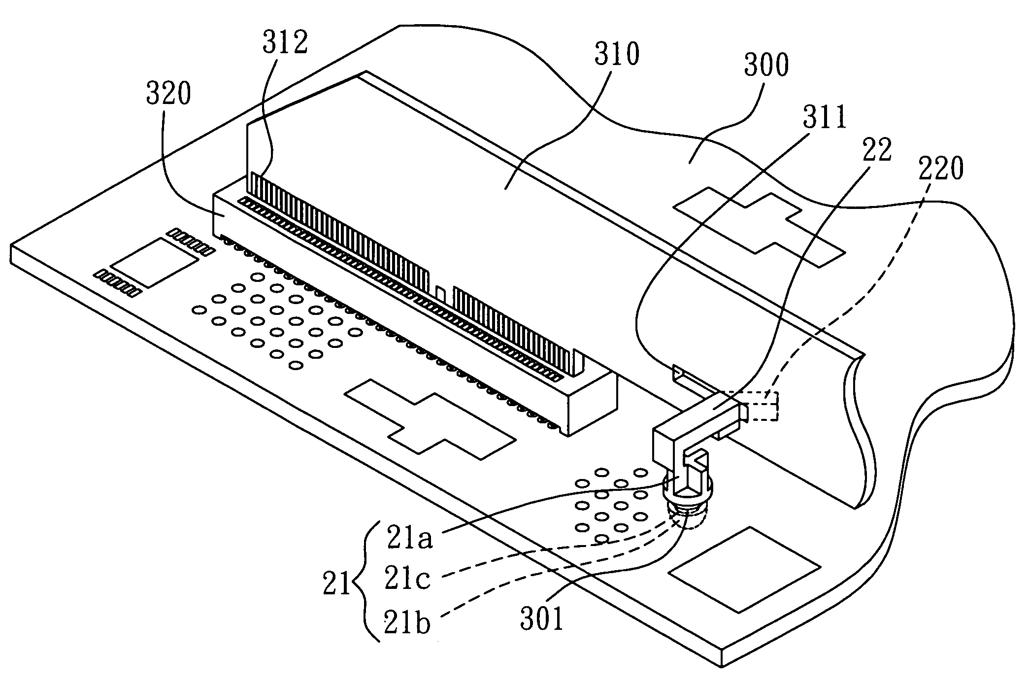
[0010]To achieve the above-mentioned and other objectives, the present invention proposes a fixing structure for an external circuit board, for fixing the external circuit board to a carrier board, the carrier board having a first opening, and the external circuit board having a second opening corresponding to the first opening. The fixing structure comprises a connecting member; and a cantilever extended from one end of the connecting member, allowing the connecting member to be coupled to the first opening of the carrier board and the cantilever to be coupled to the second opening of the external circuit board provided that the external circuit board is vertically mounted via a side thereof to the carrier board, so as to enhance connection between the external circuit board and the carrier board and avoid the external circuit board falling off from the carrier board due to shocks.
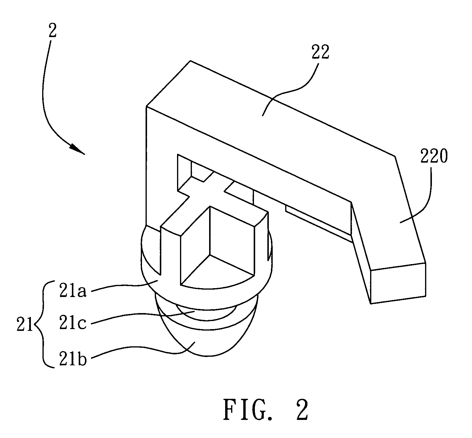
[0011]The connecting member of the fixing structure comprises a base, a fixing pin for the base, and a connecting portion formed between the base and the fixing pin. The connecting member is made of an elastic material. By a design that cross-section sizes of the base and the fixing pin of the connecting member are larger than that of the first opening of the carrier board and a cross-section size of the connecting portion of the connecting member is smaller than that of the first opening of the carrier board, when one end of the fixing pin of the connecting member is inserted in the first opening of the carrier board, the connecting portion of the connecting member can be received and fixed in the first opening, and the cantilever disposed on the end of the connecting member can be inserted in the second opening of the external circuit board that is vertically mounted to the carrier board, so as to provide a good connection effect between the external circuit board and the carrier board by means of the fixing structure.
[0012]Therefore, the fixing structure for an external circuit board according to the present invention has the connecting member coupled to the first opening of the carrier board, and allows the cantilever disposed on the end the connecting member to be coupled to the second opening of the external circuit board that is vertically inserted in the carrier board, such that the external circuit board can be effectively fixed to the carrier board and prevented from falling off from the carrier board due to external shocks. Moreover, the fixing structure of the present invention is simple in structure and is convenient in assembly and operation, thereby overcoming the drawbacks of the prior art.

Problems solved by technology

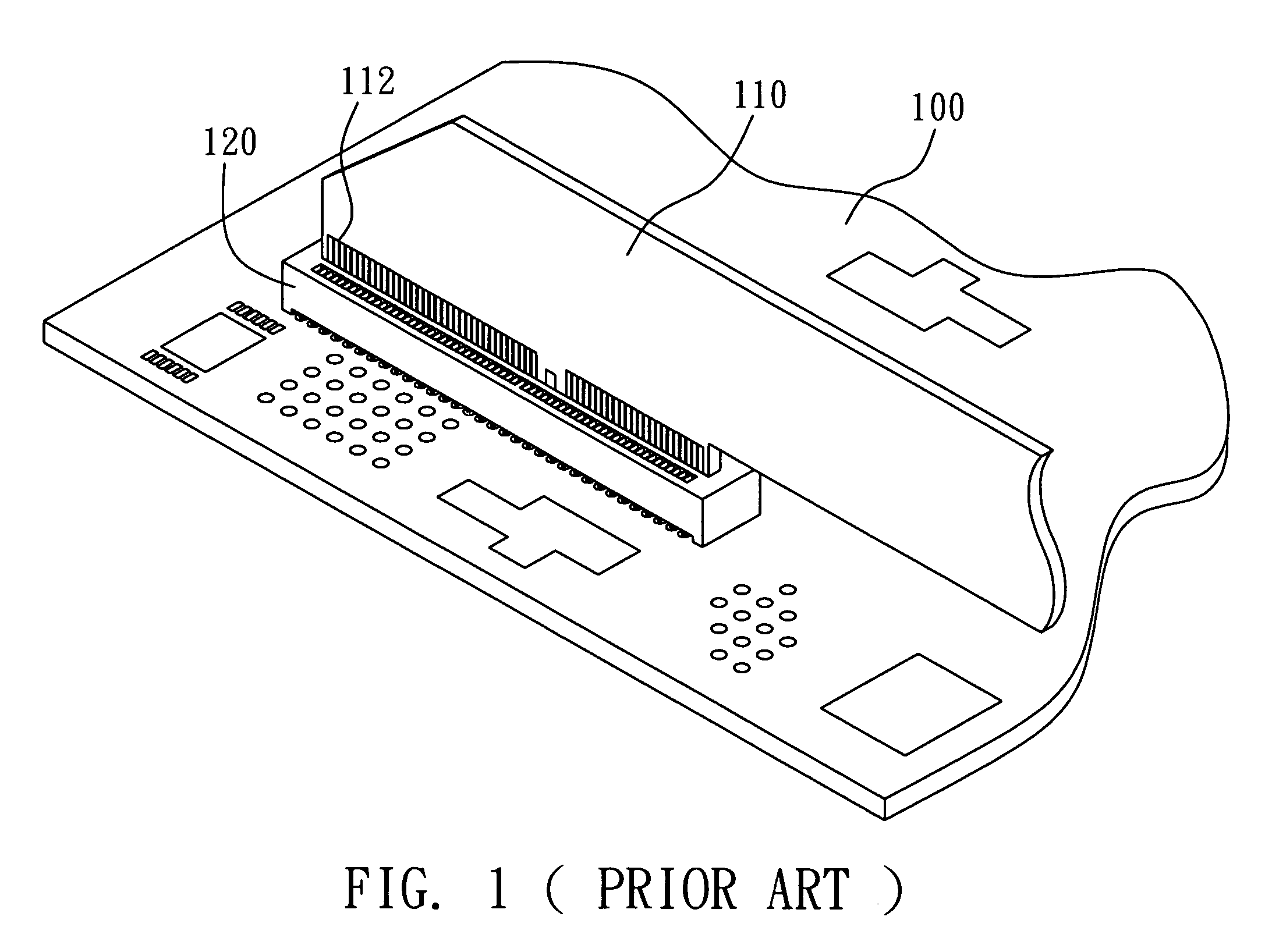
Under a condition of requiring multiple functions provided by an electronic device, a single circuit board installed in the electronic device cannot meet such requirement.
Therefore, the problem to be solved here is to provide a fixing structure for an external circuit board to avoid the external circuit board falling from a carrier board, on which the external circuit board is mounted, due to external shocks.

Method used


Image

  • Fixing structure for external circuit board
  • Fixing structure for external circuit board
  • Fixing structure for external circuit board

Examples


Embodiment Construction

[0017]Preferred embodiments of a fixing structure for an external circuit board according to the present invention are described as follows with reference to FIGS. 2 and 3. It is to be noted that the drawings are simplified schematic diagrams and only show components relating to the present invention. In practice, the layout of components could be more complicated. It should be understood that the following embodiments are not construed to limit the scope of the present invention.

[0018]As shown in FIG. 2, a fixing structure 2 for an external circuit board according to the present invention comprises: a connecting member 21, and a cantilever 22 extended from one end of the connecting member 21.

[0019]The connecting member 21 comprises: a base 21a, a fixing pin 21b for the base 21a, and a connecting portion 21c formed between the base 21a and the fixing pin 21b. A cross-sectional size of the connecting portion 21c is smaller than those of the base 21a and the fixing pin 21b. The connec...


PUM


Abstract

A fixing structure for an external circuit board is provided for fixing the external circuit board to a carrier board, the carrier board having a first opening, and the external circuit board having a second opening corresponding to the first opening. The fixing structure includes a connecting member and a cantilever extended from one end of the connecting member. When the external circuit board is vertically inserted in a connector of the carrier board, the connecting member is coupled to the first opening of the carrier board and the cantilever is coupled to the second opening of the external circuit board, such that connection between the external circuit board and the carrier board can be enhanced by means of the fixing structure to avoid the external circuit board falling off from the carrier board by shocks.

Description

FIELD OF THE INVENTION[0001]The present invention relates to fixing structures, and more particularly, to a fixing structure for an external circuit board.BACKGROUND OF THE INVENTION[0002]As the technology advances, various electronic products especially high-level servers and personal computers have been developed in accordance with demands of manufacturers and consumers.[0003]Under a condition of requiring multiple functions provided by an electronic device, a single circuit board installed in the electronic device cannot meet such requirement. Accordingly, an external circuit board is considered necessary to be used with the inherent circuit board to form a modularized structure to provide the electronic device with enhanced electrical and functional performances.[0004]FIG. 1 shows a conventional structure having an external circuit board additionally mounted to an inherent circuit board. A connector 120 is additionally formed on a printed circuit board 100 where various electron...

Claims


Application Information

Patent Timeline
IPC IPC(8): H01R13/62
CPCH01R12/721H05K7/1429H01R12/7005H05K7/142H05K3/301H05K3/366
Inventor CHANG, LIN-WEI
Owner INVENTEC CORP
Learn More