
Two-wire layered heater system

a heater system and layered technology, applied in the field of electric heaters and controllers, can solve the problems of increasing the bulkyness of the thermocouple, increasing the complexity of the overall heater system, and requiring additional electrical leads, and achieve the effect of sufficient temperature coefficient of resistance characteristics

Active Publication Date: 2007-03-27
WATLOW ELECTRIC MFG
View PDF31 Cites 264 Cited by
  • Summary
  • Abstract
  • Description
  • Claims
  • Application Information

AI Technical Summary

Benefits of technology

The present invention provides a heater system that includes a layered heater with a resistive layer that acts as a heater element and a temperature sensor. The heater system also includes a two-wire controller that determines the temperature of the heater system using the resistance of the resistive layer and controls the heater temperature accordingly. The heater system can be used in various forms such as a thick film heater, a thin film heater, a thermally sprayed heater, and a sol-gel heater. Additionally, the invention provides a method for operating the layered heater by supplying power to the heater through a set of leads and calculating the temperature of the resistive element using a two-wire controller in communication with the layered heater. The technical effects of the invention include improved heating control and efficiency, as well as improved reliability and durability of the heater system.

Problems solved by technology

However, the thermocouple is relatively bulky, requires additional electrical leads, and fails relatively frequently.
Unfortunately, the RTD also communicates with the controller through an additional set of electrical leads.
For systems that employ a large number of temperature sensors, the number of associated electrical leads for each sensor is substantial and results in added bulk and complexity to the overall heater system.
For example, one such application where electrical leads add bulk and complexity to a heater system is with injection molding systems.
Further, wiring channels are typically milled into plates of the mold system to route the leads to each nozzle, and therefore, an increased number of electrical leads adds cost and complexity to the hot runner mold system and adds bulk to the overall injection molding system.

Method used


Image

  • Two-wire layered heater system
  • Two-wire layered heater system
  • Two-wire layered heater system

Examples


Embodiment Construction

[0031]The following description of the preferred embodiments is merely exemplary in nature and is in no way intended to limit the invention, its application, or uses.

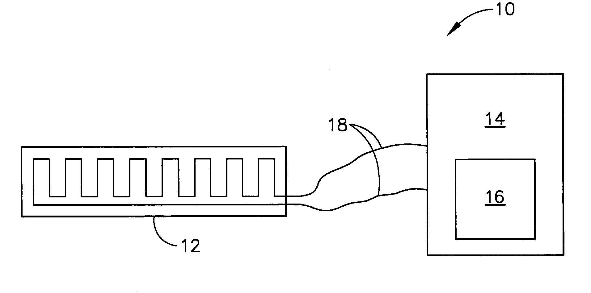
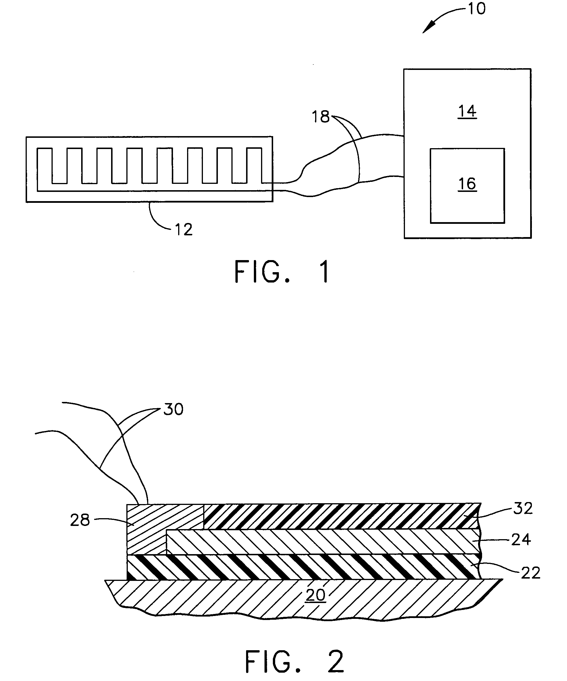
[0032]Referring to FIG. 1, a simplified heater system in block diagram format in accordance with one form of the present invention is illustrated and generally indicated by reference numeral 10. The heater system 10 comprises a layered heater 12, a two-wire controller 14, which is preferably microprocessor based, and a power source 16 within or connected to the two-wire controller 14. The layered heater 12 is connected to the two-wire controller 14 as shown through a single set of electrical leads 18. Power is provided to the layered heater 12 through the electrical leads 18, and temperature information of the layered heater 12 is provided on command to the two-wire controller 14 through the same set of electrical leads 18. More specifically, the two-wire controller 14 determines the temperature of the layered heater 12...


PUM

PropertyMeasurementUnit
conduction anglesaaaaaaaaaa
temperature coefficient of resistanceaaaaaaaaaa

Abstract

A heater system is provided with a layered heater in communication with a two-wire controller, wherein a resistive layer of the layered heater is both a heater element and a temperature sensor. The two-wire controller thus determines temperature of the layered heater using the resistance of the resistive layer and controls heater temperature through a power source. Furthermore, a heater system using a layered heater in communication with a two-wire controller for a specific application of a hot runner nozzle in an injection molding system is provided by the present invention.

Description

FIELD OF THE INVENTION[0001]The present invention relates generally to electrical heaters and controllers and more particularly to temperature sensing for layered heaters.BACKGROUND OF THE INVENTION[0002]Layered heaters are typically used in applications where space is limited, when heat output needs vary across a surface, or in ultra-clean or aggressive chemical applications. A layered heater generally comprises layers of different materials, namely, a dielectric and a resistive material, which are applied to a substrate. The dielectric material is applied first to the substrate and provides electrical isolation between the substrate and the resistive material and also minimizes current leakage during operation. The resistive material is applied to the dielectric material in a predetermined pattern and provides a resistive heater circuit. The layered heater also includes leads that connect the resistive heater circuit to a heater controller and an over-mold material that protects t...

Claims


Application Information

Patent Timeline
Patent Type & Authority Patents(United States)
IPC IPC(8): H05B3/16B29C45/27H05B1/02H05B3/26H05B3/28H05B3/42H05B3/46
CPCB29C45/2737H05B1/023H05B3/26H05B3/28H05B3/46H05B3/42B29C2045/274B29C2045/2745H05B2203/035H05B2203/002H05B2203/011H05B2203/013H05B2203/017
Inventor FENNEWALD, KENNETH F.MCDOWELL, III, WILLIAM A.PTASIENSKI, KEVINSTEINHAUSER, LOUIS P.
Owner WATLOW ELECTRIC MFG
Learn More