Radar-assisted sensing of the position and/or movement of the body or inside the body of living beings

a technology of assisted sensing and living beings, applied in the direction of instruments, lock applications, pedestrian/occupant safety arrangements, etc., can solve the problems of large amount of evaluation logic, difficult image evaluation, and higher cos

Inactive Publication Date: 2007-03-27
ROBERT BOSCH GMBH
View PDF21 Cites 105 Cited by
  • Summary
  • Abstract
  • Description
  • Claims
  • Application Information

AI Technical Summary

Benefits of technology

[0012]The heart beat can be characterized with the present invention. With the sensor according to the invention, it is possible to determine and physiologically interpret not only the pulse frequency, but also the “pumping motion” of the heart.
[0013]To measure breathing, a further strong reflection at the outer region / chest cavity junction is utilized. This signal is determined using the same method according to the invention. As a result, it is possible to simultaneously measure breathing and heart beat with the method according to the invention.
[0015]In an advantageous manner according to the invention, movements of the body or parts of the body inside the body may be determined by evaluating the receive signal and transmit signal by determining the Doppler frequency shift between the two signals. This is a simple and sufficiently accurate method for determining bodily movements.

Problems solved by technology

Image evaluation is difficult and requires a large amount of evaluation logic, however, which results in higher costs.
In addition, it is unable to determine movements inside the body, e.g., the heart beat.
Methods used in electrocardiography have the disadvantage, however, that they are not contactless, because electrodes must be placed on the body.
Infrared measurements are also unsuitable for the purposes stated above, due to their inaccuracy and poor resolution for observing processes inside the body.

Method used


Image

  • Radar-assisted sensing of the position and/or movement of the body or inside the body of living beings
  • Radar-assisted sensing of the position and/or movement of the body or inside the body of living beings
  • Radar-assisted sensing of the position and/or movement of the body or inside the body of living beings

Examples


Embodiment Construction

[0031]In the figures, the same reference numerals label components that are the same or that have the same function.

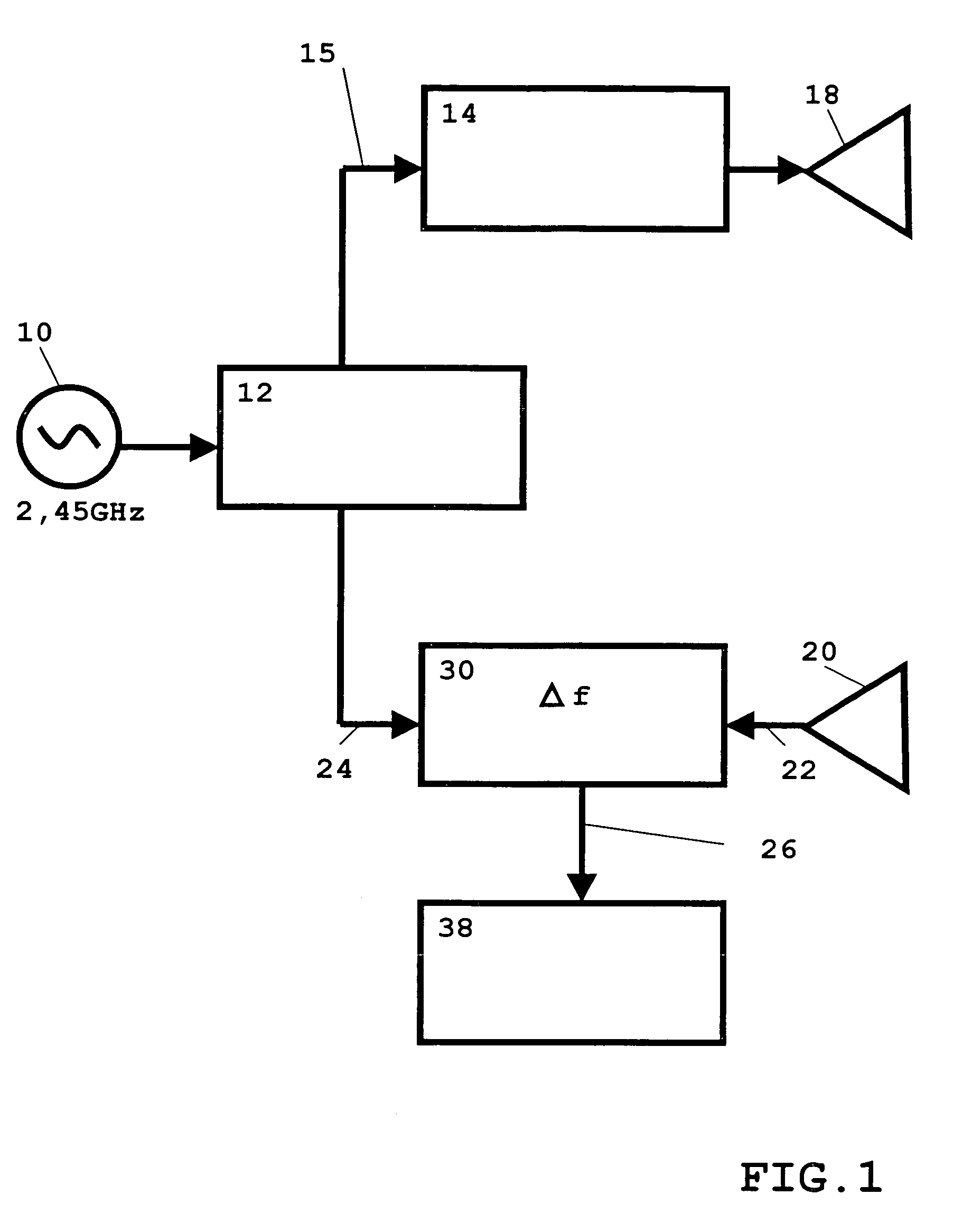
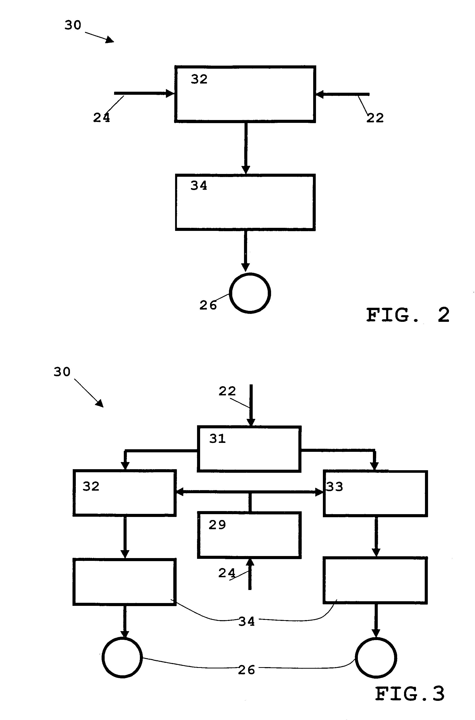
[0032]FIG. 1 shows a block diagram of the configuration of a system for sensing according to the method, according to the invention, in the embodiment of a continuous wave (CW) radar. With continuous wave radar, continuous—instead of pulsed—electromagnetic waves are used in the radar frequency range.

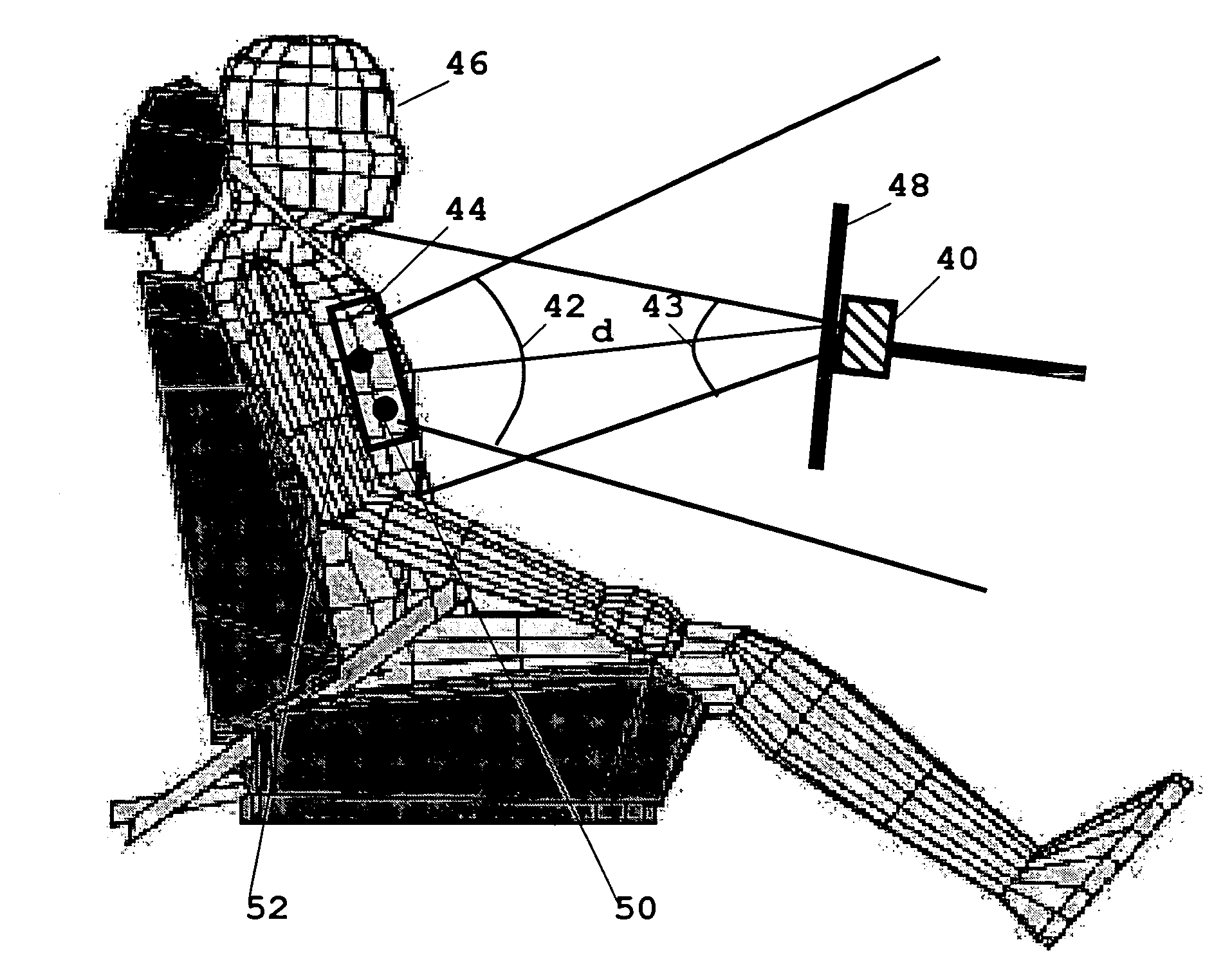
[0033]A high-frequency, continuous useful signal in the GHz range having a frequency, e.g., of 2.45 GHz and average power of approximately 1 mW is conducted from a frequency generator 10, type VCO, to a 3 dB power divider 12. The signal is split into a transmit signal 15 and a reference signal 24 in a 1:1 ratio. Transmit signal 15 travels via a band pass filter 14, which filters out all frequencies outside the ISM band (2.45 GHz+ / −50 MHz), to radar transmit antenna 18. From there, a continuous electromagnetic wave is emitted in the direction of the area of the body site to ...


PUM


Abstract

The present invention relates to a method for sensing information about the position and / or movements of the body of a living being or a part of the body inside the body, in particular for use in a motor vehicle. The method includes the steps:Send (18) an electromagnetic signal (15) that includes, according to the invention, frequencies in the radar range, to a predetermined area of the body of a living being,Receive (20) an electromagnetic signal (22) reflected from the area of the body,Evaluate (30) the captured receive signal (22) with regard for the difference in delay time and / or frequency relative to the transmit signal (15) to determine the information.With the method according to the present invention, the breathing and heart rate and the position of the body of a driver of a motor vehicle can be monitored in contactless fashion during the drive.

Description

BACKGROUND OF THE INVENTION[0001]The present invention is directed to a method for sensing information about the position and / or movements of the body of a living being or a part of the body inside the body.[0002]There is a great deal of interest in methods for detecting such information not only in the field of medical technology but also in the automotive industry in particular, because inattentiveness, falling asleep at the wheel and cardiac stress caused by stressful situations are frequent causes of accidents with fatalities. For this reason, various approaches are taken to detect physiological measurement parameters such as the heart beat, breathing and the position of the body. These parameters are evaluated and, depending on the results, warning signals can be generated. This information can be used to characterize the driver's state, or as data to control the triggering of an airbag, for example.[0003]Optical measurement methods with cameras are known in the related art for...

Claims


Application Information

Patent Timeline
Patent Type & Authority Patents(United States)
IPC IPC(8): B60Q1/00B60R21/16G01S13/00G01S13/08G08B13/00G08B21/00G08B23/00A61B5/024A61B5/113A61B5/18E05B65/19G01S7/41G01S13/56
CPCA61B5/0507E05B83/26G01S7/415G01S13/56A61B5/18A61B5/024A61B5/113G01S2007/2886G01S7/2886
Inventor RUOSS, HANS-OLIVERMAHLER, MICHAELSEIDEL, JUERGEN
Owner ROBERT BOSCH GMBH
Why Eureka
Try Eureka