Computationally efficient means for optimal control with control constraints

a control constraint and computational efficiency technology, applied in adaptive control, instruments, air-flow influencers, etc., can solve problems such as less than optimal performance, achieve maximum performance, avoid actuator saturation, and improve performance

Inactive Publication Date: 2007-03-27
SIKORSKY AIRCRAFT CORP
View PDF11 Cites 15 Cited by
  • Summary
  • Abstract
  • Description
  • Claims
  • Application Information

AI Technical Summary

Problems solved by technology

However, a constant weighting that is sufficient to ensure that no actuator ever saturates results in less than optimal performance.

Method used


Image

  • Computationally efficient means for optimal control with control constraints
  • Computationally efficient means for optimal control with control constraints
  • Computationally efficient means for optimal control with control constraints

Examples


Embodiment Construction

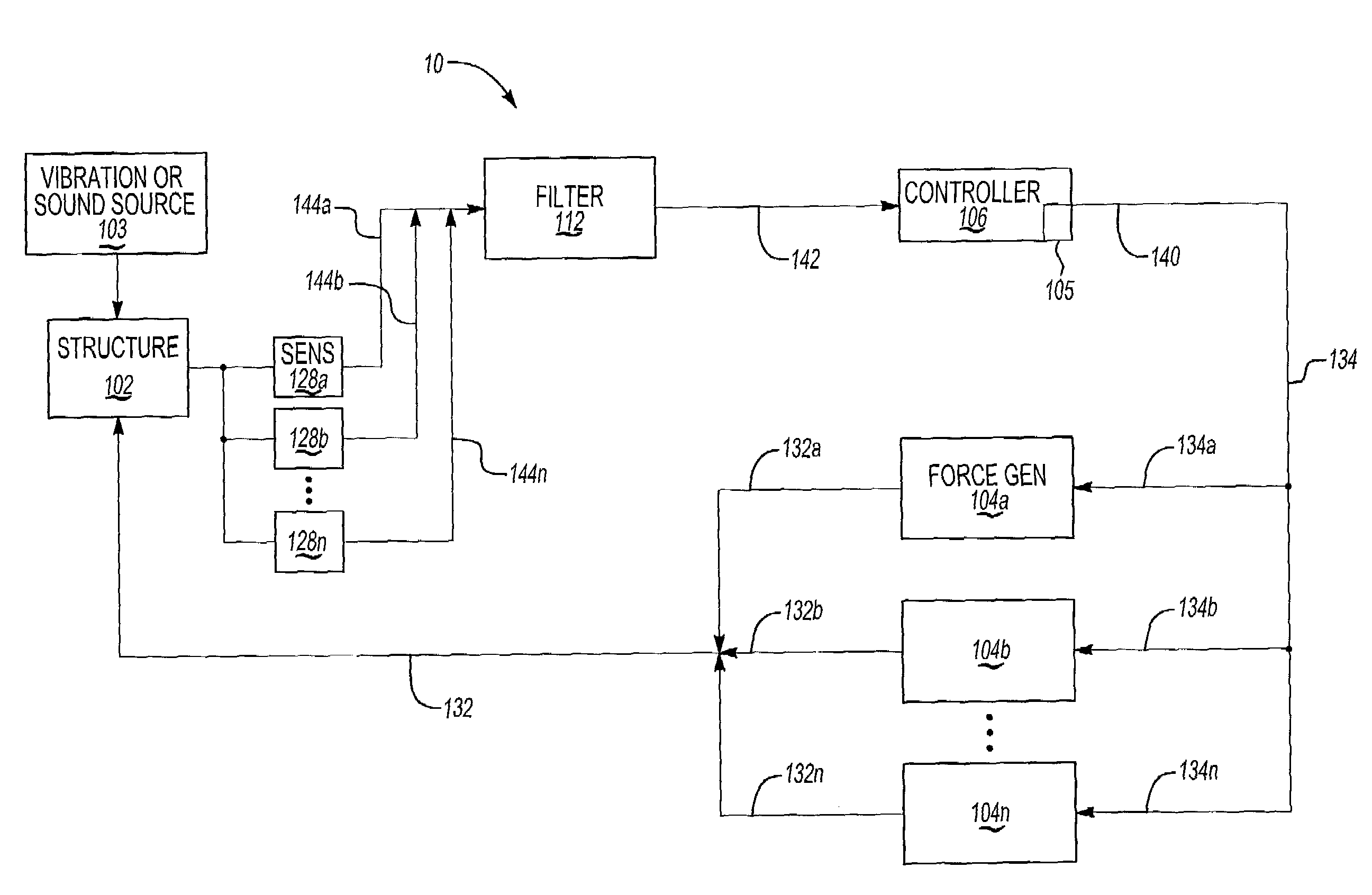
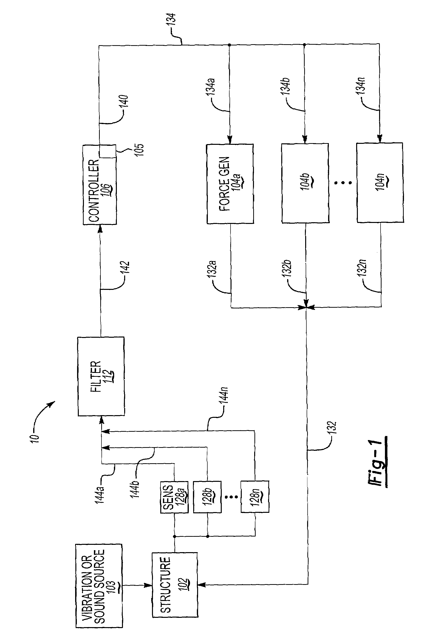
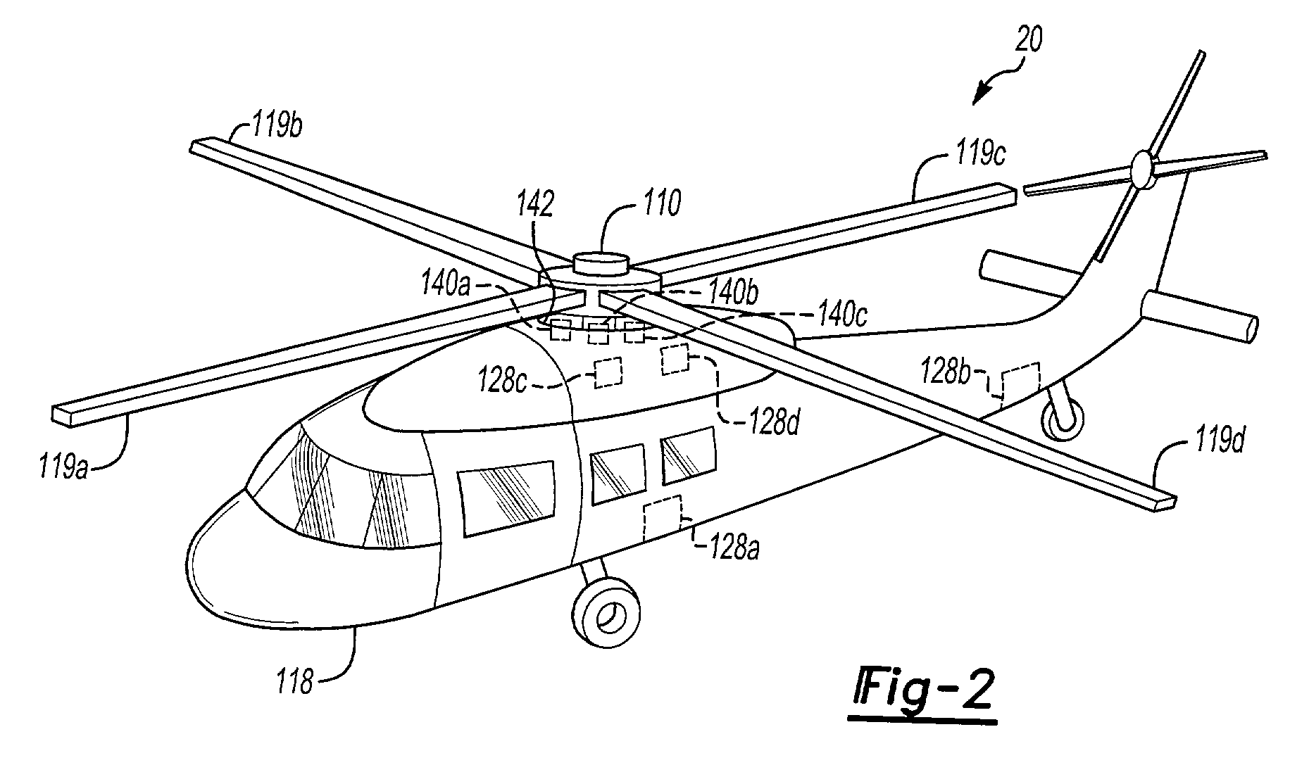
[0011]Control systems consist of a number of sensors which measure ambient vibration (or sound), actuators capable of generating vibration at the sensor locations, and a computer which processes information received from the sensors and sends commands to the actuators which generate a vibration field to cancel ambient vibration (generated, for example by a disturbing force at the helicopter rotor). The control algorithm is the scheme by which the decisions are made as to what the appropriate commands to the actuators are.

[0012]FIG. 1 shows a block diagram 10 of an active control system. The system comprises a structure 102, the response of which is to be controlled, sensors 128, filter 112, control unit 106 and actuators (which could be force generators) 104. A disturbance source 103 produces undesired response of the structure 102. In a helicopter, for example, the undesired disturbances are typically due to vibratory aerodynamic loading of rotor blades, gear clash, or other source...


PUM


Abstract

A system and method reduces undesired noise or vibration in a vehicle. The ambient vibration is measured and command signals are generated over time. The command signals are generated based upon the measured vibration and based upon a control weighting. By varying the control weighting over time, the maximum possible performance is always obtained subject to the saturation constraints.

Description

[0001]This application claims priority to U.S. Provisional Application Ser. No. 60 / 271,792, Filed Feb. 27, 2001.BACKGROUND OF THE INVENTION[0002]1. Field of the Invention[0003]This invention relates to optimal control of a system. More particularly, this invention relates to active vibration and active sound control systems for the interior of helicopters.[0004]2. Background Art[0005]Conventional active control systems consist of a number of sensors that measure the ambient variables of interest (e.g. sound or vibration), a number of actuators capable of generating an effect on these variables (e.g. by producing sound or vibration), and a computer which processes the information received from the sensors and sends commands to the actuators so as to reduce the amplitude of the sensor signals. The control algorithm is the scheme by which the decisions are made as to what commands to the actuators are appropriate.[0006]A problem may arise in such a control scheme when the control decis...

Claims


Application Information

Patent Timeline
Patent Type & Authority Patents(United States)
IPC IPC(8): G10K11/16F16F15/00F16F15/02G05B5/01G05B13/02G05D19/02G10K11/178
CPCF16F15/00F16F15/02G05B5/01G05B13/024G05D19/02G10K11/1788G10K11/1786G10K2210/503G10K2210/121G10K2210/1281G10K2210/3212G10K11/17821G10K11/17823G10K11/1783G10K11/17873
Inventor MILLOTT, THOMAS A.MACMARTIN, DOUGLAS G.GOODMAN, ROBERT K.FULLER, JAMES W.
Owner SIKORSKY AIRCRAFT CORP
Why Eureka
Try Eureka