Printer and image forming method providing selectable path for recording medium

a printing medium and image technology, applied in the field of printing media for forming images, can solve the problems of incompetence of the electrophotographic system of the printer to be applied to the mini-laboratory, troublesome processing, and cost, and achieve the effect of reducing the trouble of collecting recording sheets

Inactive Publication Date: 2007-03-27
FUJIFILM HLDG CORP +1
View PDF4 Cites 15 Cited by
  • Summary
  • Abstract
  • Description
  • Claims
  • Application Information

AI Technical Summary

Benefits of technology

[0014]In view of the foregoing, it is an object of the present invention to provide a printer and an image forming method capable of being applied to a mini-laboratory, which is concerned with an electrophotographic system and is high in working efficiency.

Problems solved by technology

However, according to such a mini-laboratory, there is a need of replenishment of developer, fixer and water, and a periodical cleaning of a tank for saving those liquids, and in addition there is a need of processing for liquid waste, which will take trouble and cost for processing.
However, an image, which is obtained through the electrophotographic system of printer, is worse than the conventional mini-laboratory in connection with an image quality such as a gloss on an image surface and thus it is not competent as a photographic image.
Accordingly, it is considered that an electrophotographic system of printer is not competent to be applied to the mini-laboratory.
The above-mentioned secondary fixing needs an extremely long processing time as compared with the primary fixing, since it takes a lot of time for a cooling of the toner image.

Method used


Image

  • Printer and image forming method providing selectable path for recording medium
  • Printer and image forming method providing selectable path for recording medium
  • Printer and image forming method providing selectable path for recording medium

Examples


first embodiment

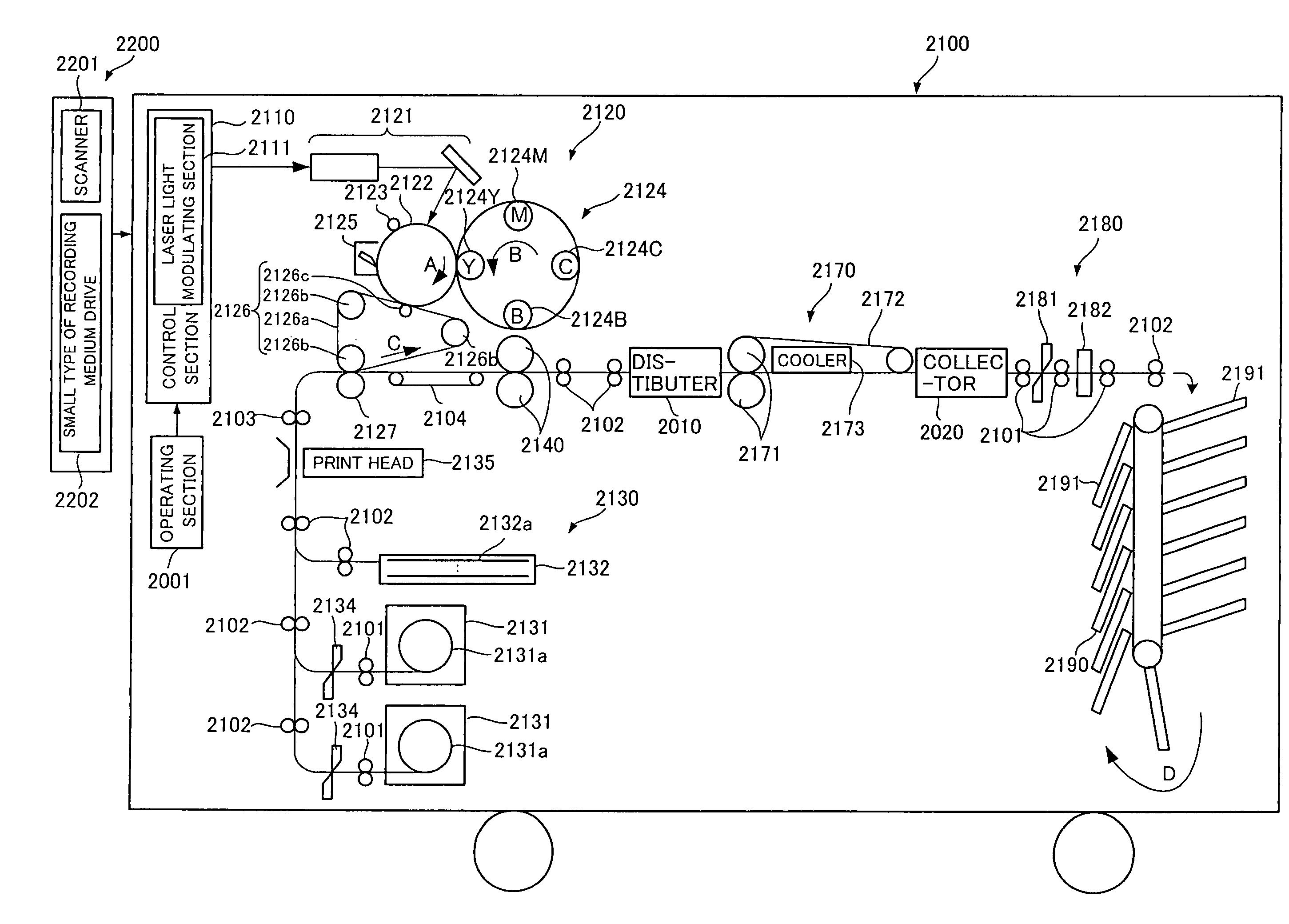
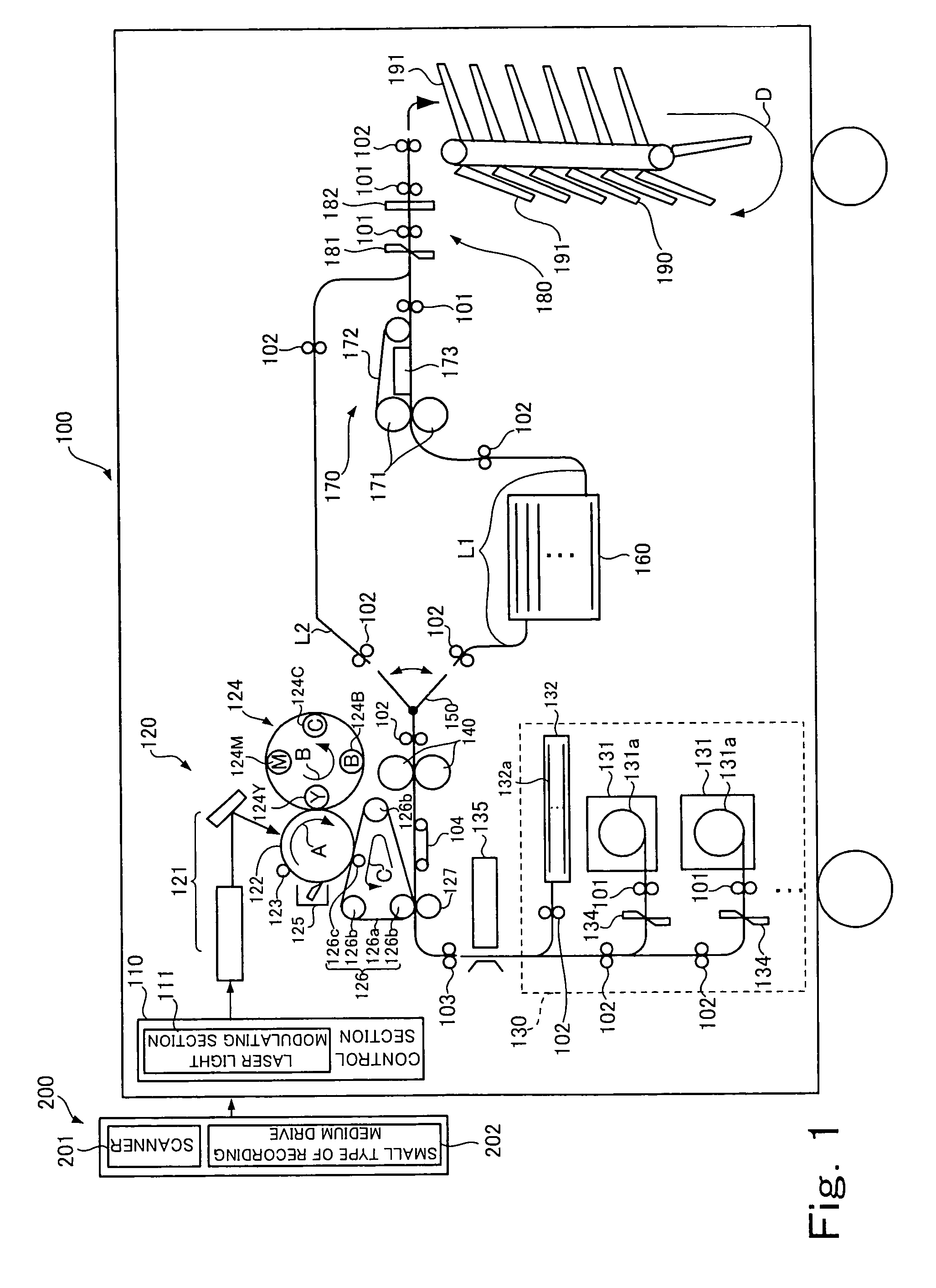
[0090]FIG. 1 is a view useful for understanding a printer according to the present invention.

[0091]FIG. 1 shows a system of a mini-laboratory comprising a printer 100 and an image input unit 200.

[0092]The image input unit 200 comprises a scanner 201 for optically reading a photographic image recorded on a photographic film to generate photographic image data, and a small type of recording medium drive 202 for reading from a small type of recording medium the photographic image data that is recorded on the small type of recording medium through photography by digital camera and the like. The image input unit 200 generates output image data through application of correcting processing such as a color tone correction and a correction for white balance to the photographic image data obtained via the scanner 201 or the small type of recording medium drive 202. The output image data thus generated is transmitted to the printer 100.

[0093]The printer 100 shown in FIG. 1 forms an image, whic...

third embodiment

[0209]FIG. 12 is a schematic structural view showing main parts of the printer which is applied to the

[0210]A printer 1200_2 according to the present embodiment shown in FIG. 12 comprises the substantially same structure elements as the printer 1200 according to the second embodiment shown in FIG. 8, excepting that the secondary fixing section 1270 of the present embodiment comprises two surface processors of a surface processor 1270_1 and a surface processor 1270_2, instead of the surface processor 1270a of the secondary fixing section 1270 in FIG. 8. Those surface processor 1270_1 and surface processor 1270_2 also comprise, in a similar fashion to that of the surface processor 1270a of the second embodiment, heating and pressure rolls 1271_1 and 1271_1, secondary fixing belts 1272_1 and 1272_2, and coolers 1273_1 and 1273_2, respectively. And those surface processors are exchangeable with various sorts of processors set forth in FIG. 9. Further, according to the present embodiment...

second embodiment

[0212]First, in similar fashion to that of the second embodiment, an operator mounts two of the surface processors shown in FIG. 9 on the secondary fixing section 1270 shown in FIG. 12. According to the present embodiment, it is assumed that the surface processor of the surface processor ID_01 is mounted as the surface processor 1270_1 and the surface processor of the surface processor ID_02 is mounted as the surface processor 1270_02.

[0213]When the surface processor 1270_1 and the surface processor ID_02 are mounted, in similar fashion to that of the step S1 in FIG. 11, the surface processors ID (ID_01, ID_02) of the surface processor 1270_1 and the surface processor ID_02 are read by a photo interrupter (not illustrated), and the surface processors ID thus read are informed the CPU 1111 shown in FIG. 7 (step S21 in FIG. 13).

[0214]Next, the operator selects an image for print out using a set-up screen prepared beforehand, and designates a sort of the sheet for print out, a print si...


PUM


Abstract

A printer includes: an image forming section that transfers a toner image onto a sheet-like recording medium conveyed on a conveyance-path, in which an electrostatic latent image is formed on a surface of an image carrier, and the toner image is formed on the surface of the image carrier by causing the electrostatic latent image to absorb toner; a primary fixing section disposed downstream of the image forming section in the conveyance-path and fixing on the recording medium the toner image transferred to the recording medium by the image forming section; a storage section disposed downstream of the primary fixing section in the conveyance-path and storing the recording medium on which the toner image is fixed by the primary fixing section; and a secondary fixing section disposed downstream of the storage section in the conveyance-path and performing a surface processing for the toner image fixed by the primary fixing section.

Description

BACKGROUND OF THE INVENTION[0001]1. Field of the Invention[0002]The present invention relates to a printer for forming an image on a recording medium in such a manner that an electrostatic latent image is formed on a surface of an image carrier, a toner image is formed on the surface of the image carrier by means of causing the electrostatic latent image to absorb toner, and transfer and fixing of the toner image are applied to the recording medium, and an image forming method of forming the image.[0003]2. Description of the Related Art[0004]Hitherto, a development of a film photographed by a camera and a print of photography are implemented in a so-called photofinishing laboratory, which is facility different-from a general store such as a photo studio. However, recently, there become popular photo studios having a small type of apparatus (hereinafter it is referred to as a mini-laboratory) for carrying out processing from printing to development necessary for printing of photograp...

Claims


Application Information

Patent Timeline
Patent Type & Authority Patents(United States)
IPC IPC(8): G03G15/20G03G15/01
CPCG03G15/2064
Inventor NAKAMURA, HIROAKIKITO, EIICHI
Owner FUJIFILM HLDG CORP
Why Eureka
Try Eureka