Radiative focal area antenna transmission coupling arrangement

a technology of transmission coupling and radio frequency emission, applied in the field ofdocking system, can solve problems such as extraneous radio frequency emission, and achieve the effect of restricting propagation

Inactive Publication Date: 2007-03-27
AMBIT ENERGY +1
View PDF3 Cites 13 Cited by
  • Summary
  • Abstract
  • Description
  • Claims
  • Application Information

AI Technical Summary

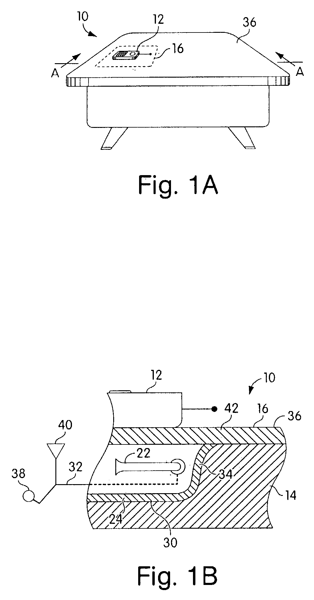
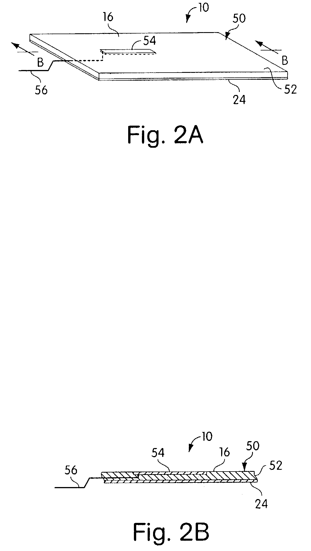
Benefits of technology

[0006]The proliferation of these hand-held devices is evident everywhere. A single hand-held device however, should able to travel with its owner and be easily transferably usable in automobiles, planes, cabs or buildings (including hospitals) as well as at offices and at desks with no restrictions on their use, and without causing concern with regard to the radiation therefrom. The hand-held devices should be portable for a user to carry in his pocket, yet be able to use that same cellular unit in such vehicle or building while minimizing such radiational effect therein.
[0007]It is an object of the present invention to permit a user of a portable hand-held electronic communication device such as a cellular telephone or the like, to conveniently use that same hand-held device / cellular phone in an automobile, plane or building, office / desk, or anywhere signal transmission is needed, and to permit such signal to reach its intended destination such as a communications network or satellite, without interfering with other electrical equipment and in spite of interfering walls of buildings or structure and / or other electrical equipment.
[0008]It is a further object of the present invention to minimize any radiation from such a portable device, such as a cellular telephone or the like, while such use occurs in an automobile, a building or an elevator, an airplane, a cab, or other public facility in which the user wishes to minimize his own exposure to stray radiation, and also to permit re-transmission of his signal, to avoid the necessity of connecting and disconnecting cables, and to permit a wide variety of cellular telephones such as would be utilized in a rental car where various manufactures' phones would be used, and to permit control of such re-transmission of signals where desired, so as to allow user / customer billing and monitoring thereof.BRIEF SUMMARY OF THE INVENTION
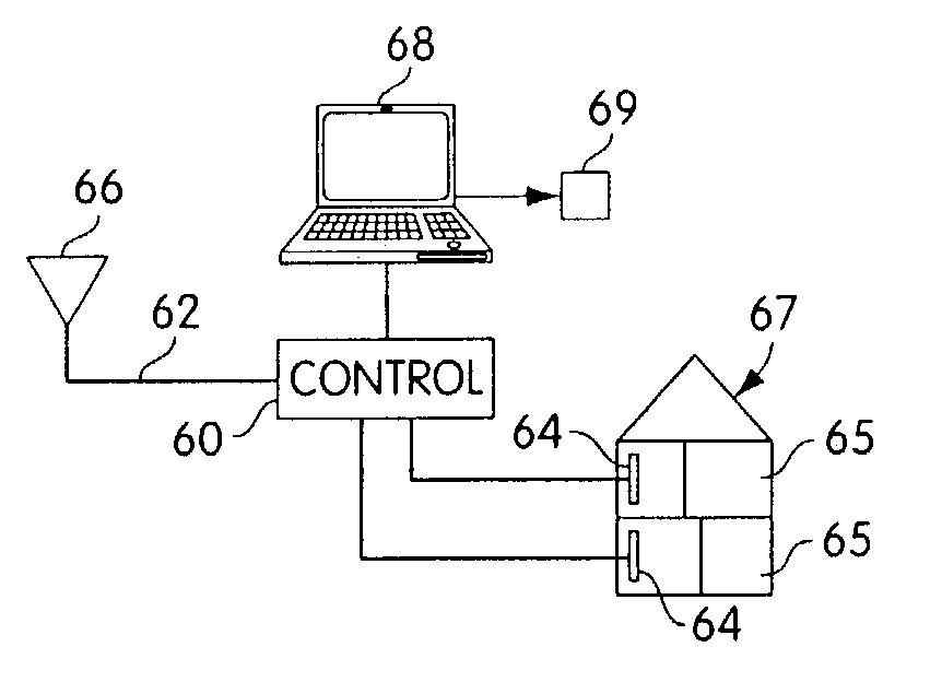
[0010]The docking system may comprise a “zone” or “focal area” as a generally rectilinear area / volume on / in a desk or work surface on / in which the electronic communication device may be placed, such a surface or space being possible on a desk, or in a plane. That focal area may also, in a further embodiment, be comprised of one or more rooms in a building, such focal area having a pick-up probe thereat, in conjunction with a shield placed on / in the desk, room, vehicle or building to prevent the radiation from that communication device from traveling in any undesired directions within the desk, room, vehicle or building.
[0011]The focal area may be defined by a metal walled structure within or on which a broadband probe is arranged. The metal walled structure acts as a shield to minimize radiation from the communication device from passing therethrough. In a first embodiment, the shield may be comprised of a partial housing disposed within the upper work surface of a desk. The probe would be elongatively disposed within the partial housing and be in electrical communication with a transmission line such as coax cable, waveguide, or the like. The partial housing may have a planar dielectric layer thereover, which would also be co-planar with the surface of the desk. The communication device would be placed within the pickup zone of the focal area, and would be able to transmit and receive signals through the dielectric layer. The partial housing would act as the shield in the desk, to minimize radiation by the worker at the desk. In a further embodiment, the housing may be comprised of a thin, generally planar mat of conductive material, which mat may be flexible and distortable, for conformance to a particular work surface and for ease of storage capabilities. The mat has an upper layer of dielectric material (for example, plastic, foam or the like). A thin, flat, conformable coupling probe may be embedded into or printed onto the upper surface of the dielectric material. The mat may be utilized as a portable focal area for placement of a communication device thereon, or wrapped up in an enveloping manner therein.

Problems solved by technology

Extraneous radio frequency emission has become a serious concern of hand-held electronic communication devices such as portable facsimile machines, ground position indicators, and cellular telephone manufacturers and users alike.

Method used


Image

  • Radiative focal area antenna transmission coupling arrangement
  • Radiative focal area antenna transmission coupling arrangement
  • Radiative focal area antenna transmission coupling arrangement

Examples


Embodiment Construction

[0024]Referring now to the drawings in detail, and particularly to FIG. 1a, there is shown a portable communication device docking arrangement 10, to permit a portable communication device such as a hand-held cellular telephone 12 to be utilized thereon, such as on a desk 14 or adjacent to it, and as a personal communicator (i.e. cellular telephone, facsimile machine, pager or the like) which may also be carried on an individual.

[0025]Such a docking system 10 of the present invention may also be adaptable to an automobile, plane, or building for providing radiationally restrictive communication between a portable electronic communication device 12 such as a cellular telephone, portable computer, facsimile machine, pager, or the like, while allowing communicative mating of the radiative antenna of that device to a further transmission line and communication system and / or a more remote antenna, as recited and shown in our aforementioned patent applications, incorporated herein by refe...


PUM


Abstract

The present invention comprises a docking system for connecting a portable communication device to a further signal transmission line. The docking system may be arranged within a workstation such as a desk or a tray. The system may also envelope a room in a building or be located in a vehicle, to control and restrict the radiative emission from the communication device and to direct such radiation to a further remote antenna and or signal distribution system connected to the transmission line.

Description

BACKGROUND OF THE INVENTION[0001](1) Field of the Invention[0002]This invention relates to a docking system for hand-held electronic communication devices such as cellular telephones or the like, for use with structures or vehicles, and is a Continuation-In-Part Application of U.S. patent application Ser. No. 08 / 581,065, filed Dec. 12, 1995 now U.S. Pat. No. 5,711,014, which is a Continuation-In-Part Application of our allowed U.S. patent application Ser. No. 08 / 042,879, filed Apr. 5, 1993 now U.S. Pat. No. 5,493,702, each being incorporated herein by reference, in their entirety.[0003]This application is also a continuation application of our U.S. patent application Ser. No. 08 / 604,105 filed Feb. 20, 1996, now U.S. Pat. No. 6,594,471, issued Jul. 15, 2003, and our U.S. patent application Ser. No. 09 / 634,140 filed Aug. 8, 2000, now U.S. Pat. No. 6,885,845, issued Apr. 26, 2005, each of which applications and patents are incorporated by reference in their entirety.[0004](2) Prior Art...

Claims


Application Information

Patent Timeline
Patent Type & Authority Patents(United States)
IPC IPC(8): H04B1/38H01Q1/24
CPCH01Q1/241H04M1/04H04B1/3877H01Q1/243B60R2011/0012H04B1/3833
Inventor CROWLEY, ROBERT JHALGREN, DONALD N.
Owner AMBIT ENERGY
Why Eureka
Try Eureka