
T-top outrigger holder apparatus

a technology of holder and t-top, which is applied in the field of fishing equipment, can solve the problems of difficulty in operation, difficulty in adjusting the holder, etc., and achieve the effect of convenient manipulation

Active Publication Date: 2007-04-03
EASTERN METAL SUPPLY
View PDF10 Cites 15 Cited by
  • Summary
  • Abstract
  • Description
  • Claims
  • Application Information

AI Technical Summary

Benefits of technology

[0010]We have invented an outrigger holder which is easy to manipulate to move the outrigger held thereby from inboard to outboard positions and back; all from under the cover of a T-top boat. This ease of movement is provided by a new structure which eliminates having the weight of the outrigger borne by the indexing means.

Problems solved by technology

One of the problems presented by these devices is the awkwardness and strength needed in operating them.

Method used


Image

  • T-top outrigger holder apparatus
  • T-top outrigger holder apparatus
  • T-top outrigger holder apparatus

Examples


Embodiment Construction

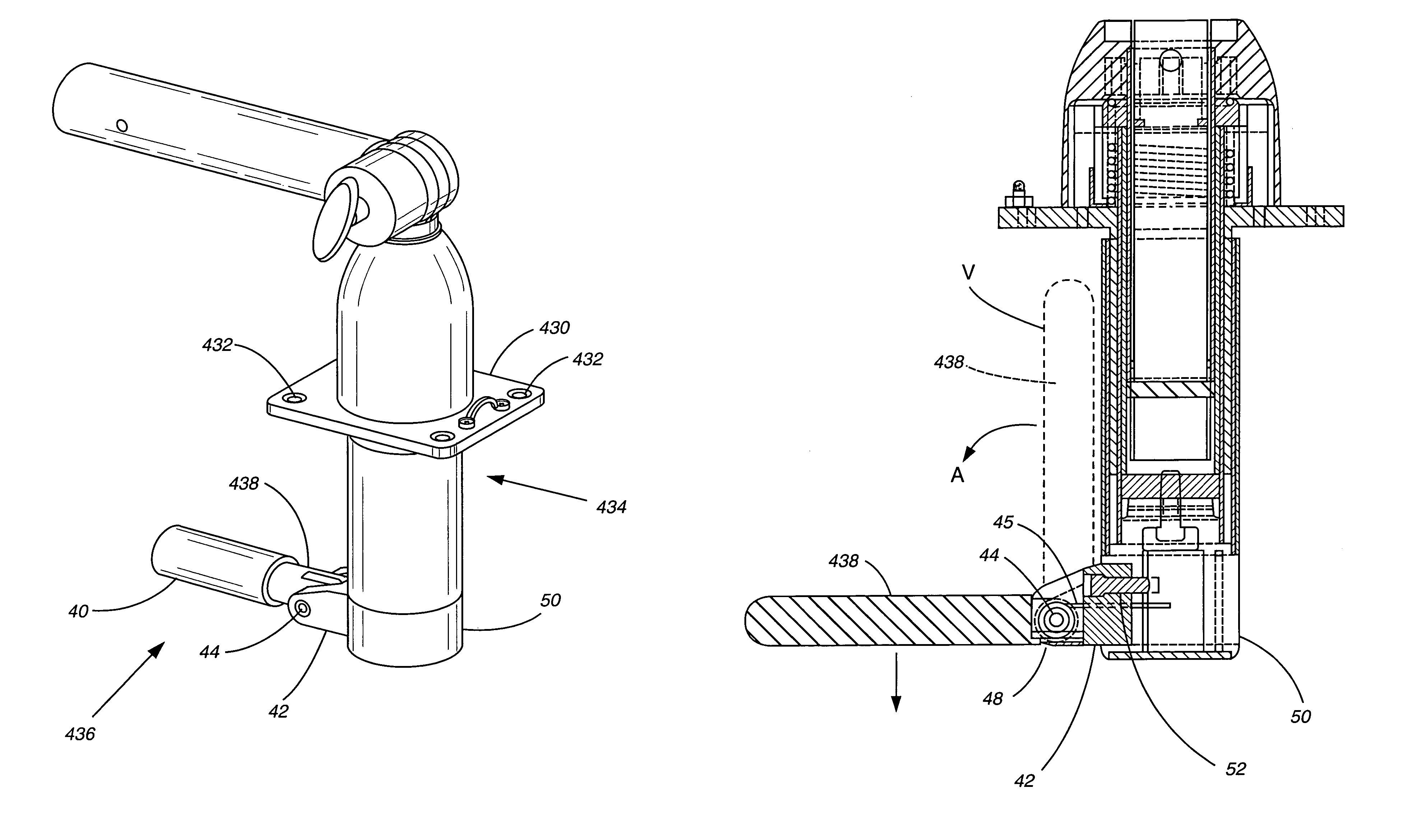
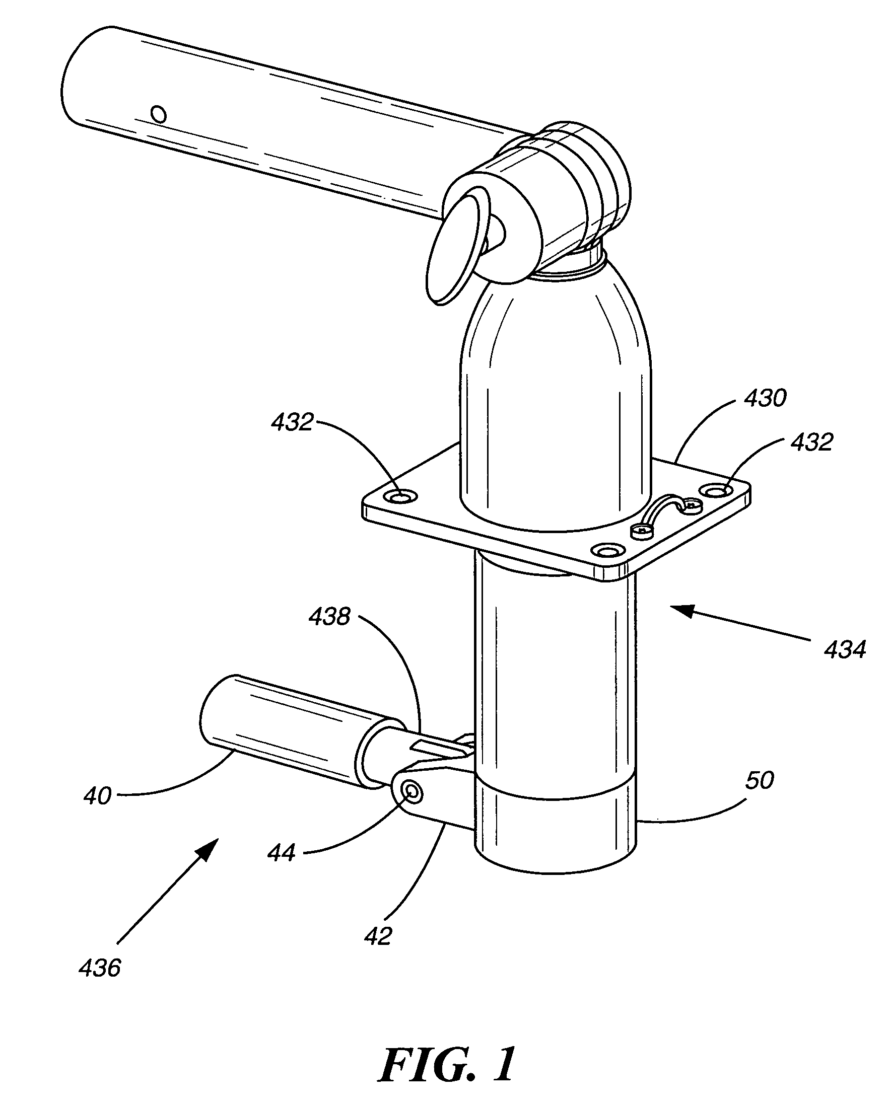
[0050]Referring to the Figures, FIG. 1 shows a perspective view of an apparatus in accordance with our invention which comprises a mounting plate 430 suitable for mounting on top of a T-top on a boat. The four mounting holes 432 shown at the corners are for receiving bolts. The lower portion designated generally 434 would be positioned below the T-top. The handle means designated generally 436 comprises a handle portion 438 and a resilient handle gripping cover 40. The handle is mounted in a hinge block 42 by means of a bolt 44. The handle is spring-biased, so as to rotate about the bolt to a vertical position “V” shown in phantom lines in FIG. 3. It can then be moved in the direction of the arrow A to its furthest extreme in the position shown in full lines in FIG. 3, wherein the bottom of the handle butts up against the hinge block 42 and prevents further rotation. The biasing spring 45 engages in the hole 46. The spring is wound about the bolt 44 and is connected to, or otherwise...


PUM


Abstract

An outrigger holder for mounting on the top of a T-Top configured boat, has a bearing mechanism mounted above the T-Top designed to relieve most of the weight of the outrigger when turning the holder and outrigger to alternate positions.

Description

CROSS REFERENCE TO RELATED APPLICATIONS[0001]This application claims the benefit of the filing date of our prior co-pending provisional application No. 60 / 455,982, filed Mar. 19, 2003, the disclosure of which is incorporated herein by reference as if fully set forth.BACKGROUND OF THE INVENTION[0002]1. Technical Field[0003]This invention relates to fishing equipment and, more particularly, to an outrigger holder apparatus for use in association with boats fitted with so-called “T-tops”.[0004]2. Description of the Prior Art[0005]In the prior art of sport fishing equipment, it is known to use outriggers to play out trolling lines away from the sides and back of the boat. These outriggers can be moved in line with the hull and in-board of the boat when they are not being used for trolling. Thus, they are adjustable between the trolling position and the storage position.[0006]These outriggers can be mounted on bases which are either fixed to the gunnels or tops of the boats or are fixed ...

Claims


Application Information

Patent Timeline
IPC IPC(8): A01K97/10B63B35/14B63B17/02
CPCB63B17/02B63B35/14
Inventor WILCOX, ROGERWILCOX, SCOTT A.GATLIN, MICHAEL J.SUAREZ, ROBERTO M.HALL, III, JOHN T.
Owner EASTERN METAL SUPPLY
Learn More